Light quantity adjusting device

a technology of light quantity and adjustment device, which is applied in the direction of camera diaphragms, shutters, instruments, etc., can solve the problems of reducing the diameter of the rotor shaft, affecting the bearing action, etc., and achieves stable bearing action and simple structure.

Inactive Publication Date: 2007-12-27
NISCA KK
View PDF8 Cites 14 Cited by
  • Summary
  • Abstract
  • Description
  • Claims
  • Application Information

AI Technical Summary

Benefits of technology

[0018]The electromagnetic driver is located so that the first shaft end of the rotor shaft is closer to the substrate. An arm is coupled to the first shaft end of the rotor shaft to transmit an opening and closing driving force to the blade. This allows the rotor shaft to be positioned and supported by the pointed first shaft end and the conical bearing recess. The above configuration minimizes the possibility that the blade is jolted or hunted when a jolt occurs between the second shaft end, the other end, and the cylindrical bearing hole.
[0019]Further, the rotor shaft has urging means for urging the rotor shaft so as to press the first shaft end against the bearing recess. The urging means comprises a magnetic attractive force that acts on the rotor shaft. This enables a stable bearing action to be achieved using the simple structure.
[0020]The urging means may comprise a yoke of a soft magnetic material located on an outer periphery of a magnet rotor to exert a magnetic urging force on the rotor shaft. Moreover, the first shaft end is formed as a spherical projecting curved surface, and the bearing recess is formed like a conical recessed curved surface that fits the spherical projecting curved surface. The radius of curvature of the recessed curved surface is set larger than that of the projecting curved surface minimizing the possibility that a dimensional error resulting from molding of the rotor shaft hinders the bearing of the rotor shaft.

Problems solved by technology

A problem in reducing the size of the driving section is how to bear the rotating shaft of the magnetic rotor (hereinafter referred to as a “rotor shaft”) by means of a frame such as the coil frame.
This results in a heavy frictional load on the bearing.
Unfortunately, a reduction in the shaft diameter of the rotor shaft may also lead to frequent jolts of the rotor shaft in the bearing hole.
It is difficult to machine the components so as to form an appropriate gap in the fitting portion.
Such a clearance is required for smooth rotations, and it is considered to be almost impossible to maintain the machining accuracy necessary for a uniform clearance.
For example, when machining is performed so that the rotor shaft has a circularity and an outer diameter accurate to at least 1 / 100 mm, costs and the number of failures in a manufacturing process increase.
Then, when the lower end of the rotor shaft is pivotally supported and the arm is provided at the upper end to drivingly open and close the blade, as in the prior art, the following problem may occur.
When a jolt occurs between the rotor shaft and the blade, if the blade performs, for example, a shutter operation, then disadvantageously, an optical path aperture cannot be fully closed or opened.
Further, if the blade performs a restricting operation, then disadvantageously, the quantity of light cannot be adjusted to a value meeting photographing conditions or hunting may occur during operation to vibrate the blade, which becomes uncontrollable making the apparatus defective.

Method used


Image

  • Light quantity adjusting device
  • Light quantity adjusting device
  • Light quantity adjusting device

Examples


Embodiment Construction

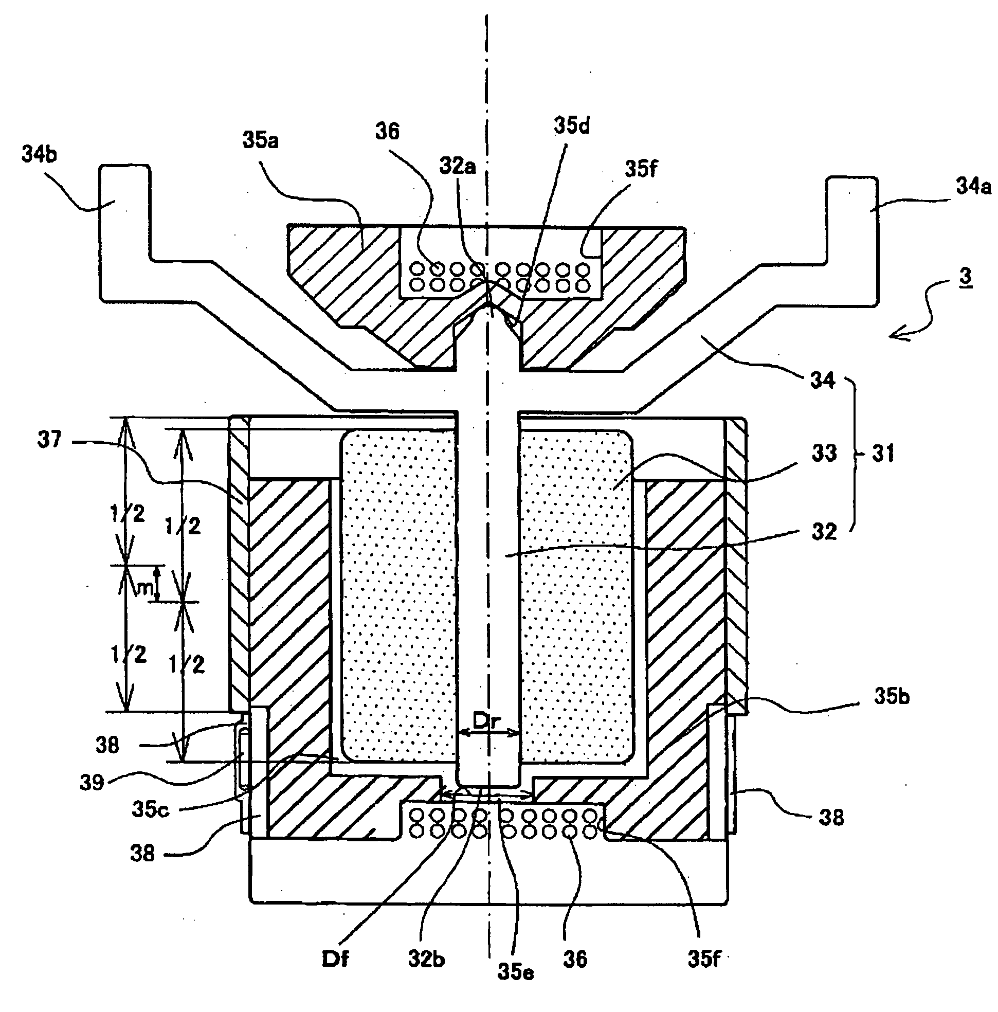
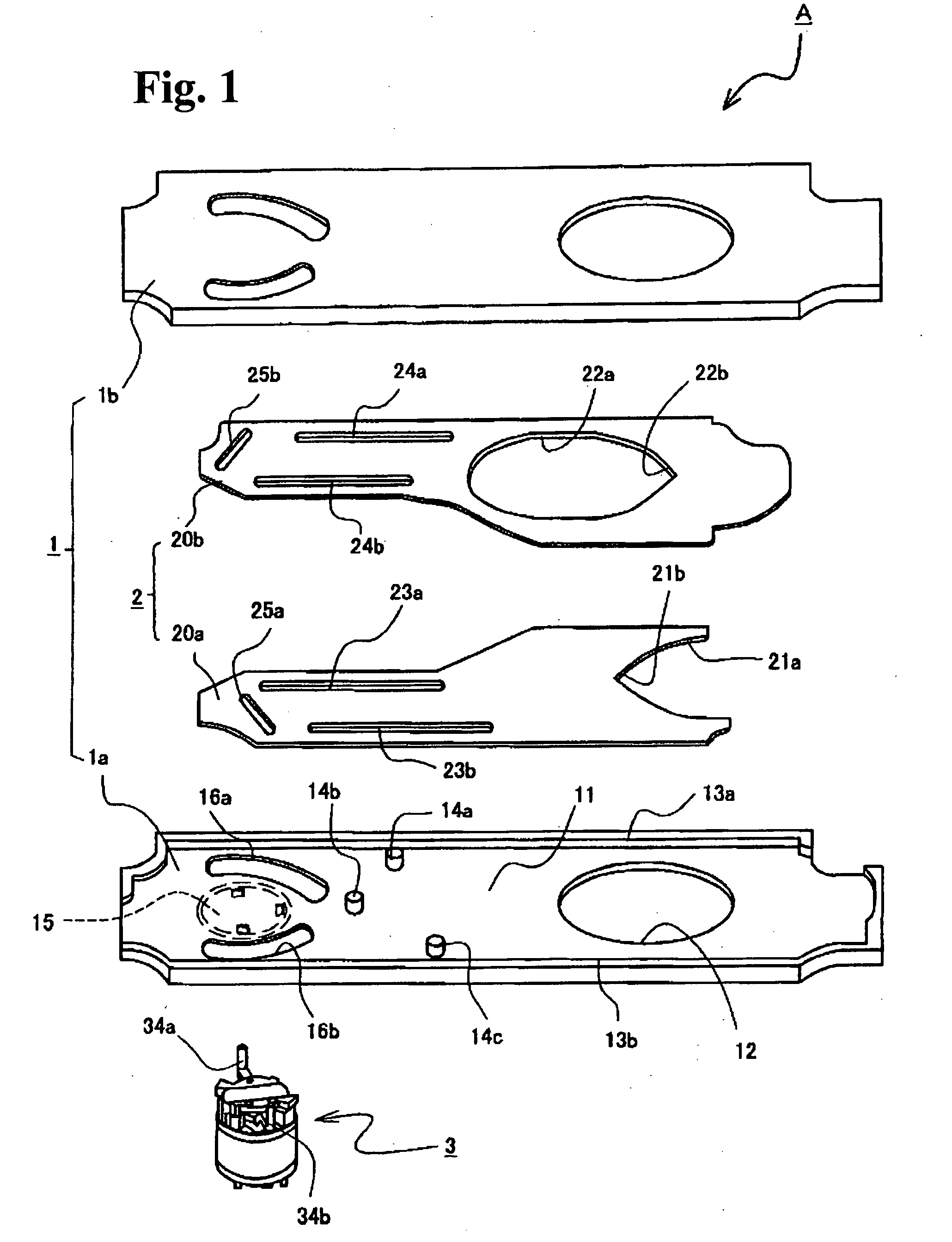
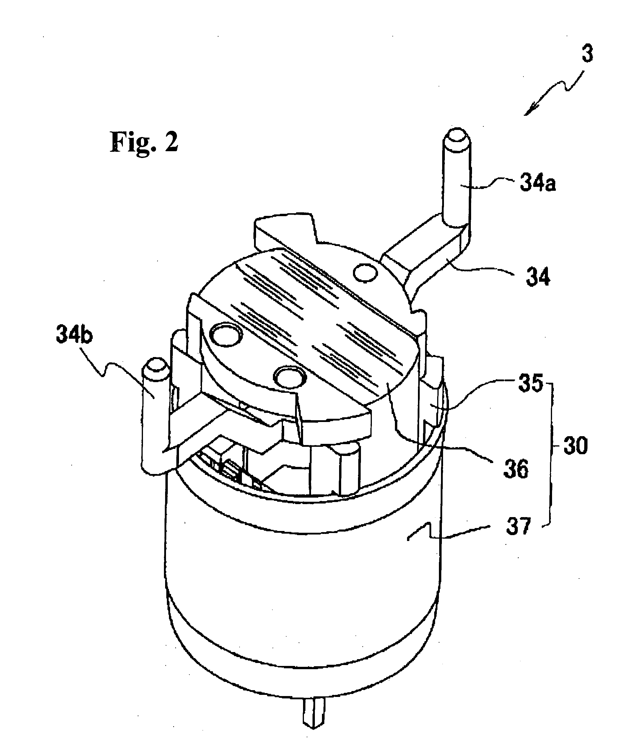
[0035]The present invention will be described on the basis of an illustrated preferred embodiment. FIG. 1 is an exploded perspective view of a light quantity adjusting device in accordance with the present invention. FIG. 2 is a perspective view of an electromagnetic driver that drivingly opens and closes a blade. FIG. 3 is a vertical sectional view of the electromagnetic driver.

[0036]The general configuration of a light quantity adjusting device A will be described with reference to FIG. 1. As shown in FIG. 1, the light quantity adjusting device in accordance with the present invention is composed of a substrate 1, a blade 2, and a driver 3. The substrate 1 is composed of a flat base plate 1a and a retainer plate 1b laid on top of the base plate 1a with a small gap formed between the base plate 1a and the retainer plate 1b. The base plate 1a is shaped to be incorporated in a space in a camera into which a photographing lens barrel is incorporated. The base plate 1a is formed by, fo...


PUM


Abstract

A light quantity adjusting device includes a substrate having an optical path aperture, a blade located on the substrate to adjust the quantity of light passing through the optical path aperture, and an electromagnetic driver that drivingly opens and closes the blade. The electromagnetic driver includes a rotor shaft, an exciting coil, and a frame that rotatably bears the rotor shaft. The rotor shaft includes a pointed first shaft end and a cylindrical second shaft end. The frame has a conical bearing recess that supports the first shaft end and a cylindrical bearing hole that supports the second shaft end. The electromagnetic driver is located so that the first shaft end of the rotor shaft is closer to the substrate than the second shaft end. An arm is coupled to the first shaft end of the rotor shaft to transmit an opening and closing driving force to the blade.

Description

BACKGROUND OF THE INVENTION AND RELATED ART STATEMENT[0001]The present invention relates to light quantity adjusting devices provided in still cameras, video cameras, or other image pickup apparatus that open and close blades, such as shutter blades or diaphragm blades, to adjust the quantity of photographing light.[0002]In general, these light quantity adjusting devices adjust the quantity of light for use by a shutter or a diaphragm by operation of an electromagnetic driver to open and close a blade located on a photographing optical axis of a camera or the like. The electromagnetic driver is composed of a magnet rotor having a permanent magnet and a rotating shaft provided in the center of the permanent magnet, and a stator having a coil frame and an exciting coil wound around the outer periphery of the coil frame. The electromagnetic driver energizes the exciting coil to rotate the magnet rotor by a predetermined angle to open and close the blade.[0003]There has been a strong de...

Claims


Application Information

Patent Timeline
Patent Type & Authority Applications(United States)
IPC IPC(8): G03B9/02
CPCG03B9/24G03B9/06
Inventor FUKASAWA, YOSHIMI
Owner NISCA KK
Why Eureka
Try Eureka