
Physiological status monitoring system

a physiological monitoring and status technology, applied in the field of physiological monitoring systems, can solve the problems of not being comfortable to wear, not meeting the needs of the marketplace, and other problems, and achieve the effects of convenient use, convenient cleaning, and comfortable wear

Inactive Publication Date: 2007-12-27
FOSTER-MILLER
View PDF103 Cites 296 Cited by
  • Summary
  • Abstract
  • Description
  • Claims
  • Application Information

AI Technical Summary

Benefits of technology

[0007] It is a further object of this invention to provide such a system which is preferably garment based and comfortable to wear.
[0008] It is a further object of this invention to provide such a system which is easy to use.
[0011] It is a further object of this invention to provide such a system which does not require the user to secure electrodes to her body or to use any conductive gels.
[0014] It is a further object of this invention to provide such a system which can be more easily cleaned.
[0015] The subject invention results from the realization that a better physiological monitoring garment such as a shirt includes a stretchable circumferential band including both a respiration sensing subsystem and signal / power transmission conductors for one or more other sensors also on the band and an easily removable electronics module electrically connected to the respiration sensing subsystem and the sensors via the band for transmitting signals representing the wearer's respiration rate and / or depth, heart rate, and the like but without any loose wires, separate electrodes, and therefore comfortable to wear, easy to use, and easily washed or cleaned.

Problems solved by technology

To date, however, no commercial product seems to meet the needs of the marketplace.
That is, some physiological monitoring systems are not comfortable to wear.
Others are difficult to use.
Some physiological monitoring garments are simply not aesthetically pleasing.
Others interfere with the activities of and duties carried out by the wearer.

Method used


Image

  • Physiological status monitoring system
  • Physiological status monitoring system
  • Physiological status monitoring system

Examples


Embodiment Construction

[0070] Aside from the preferred embodiment or embodiments disclosed below, this invention is capable of other embodiments and of being practiced or being carried out in various ways. Thus, it is to be understood that the invention is not limited in its application to the details of construction and the arrangements of components set forth in the following description or illustrated in the drawings. If only one embodiment is described herein, the claims hereof are not to be limited to that embodiment. Moreover, the claims hereof are not to be read restrictively unless there is clear and convincing evidence manifesting a certain exclusion, restriction, or disclaimer.

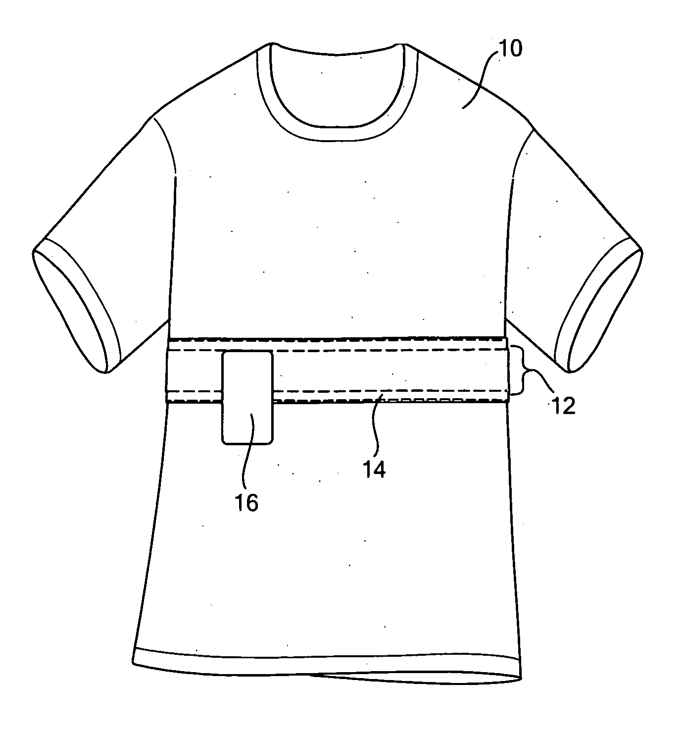
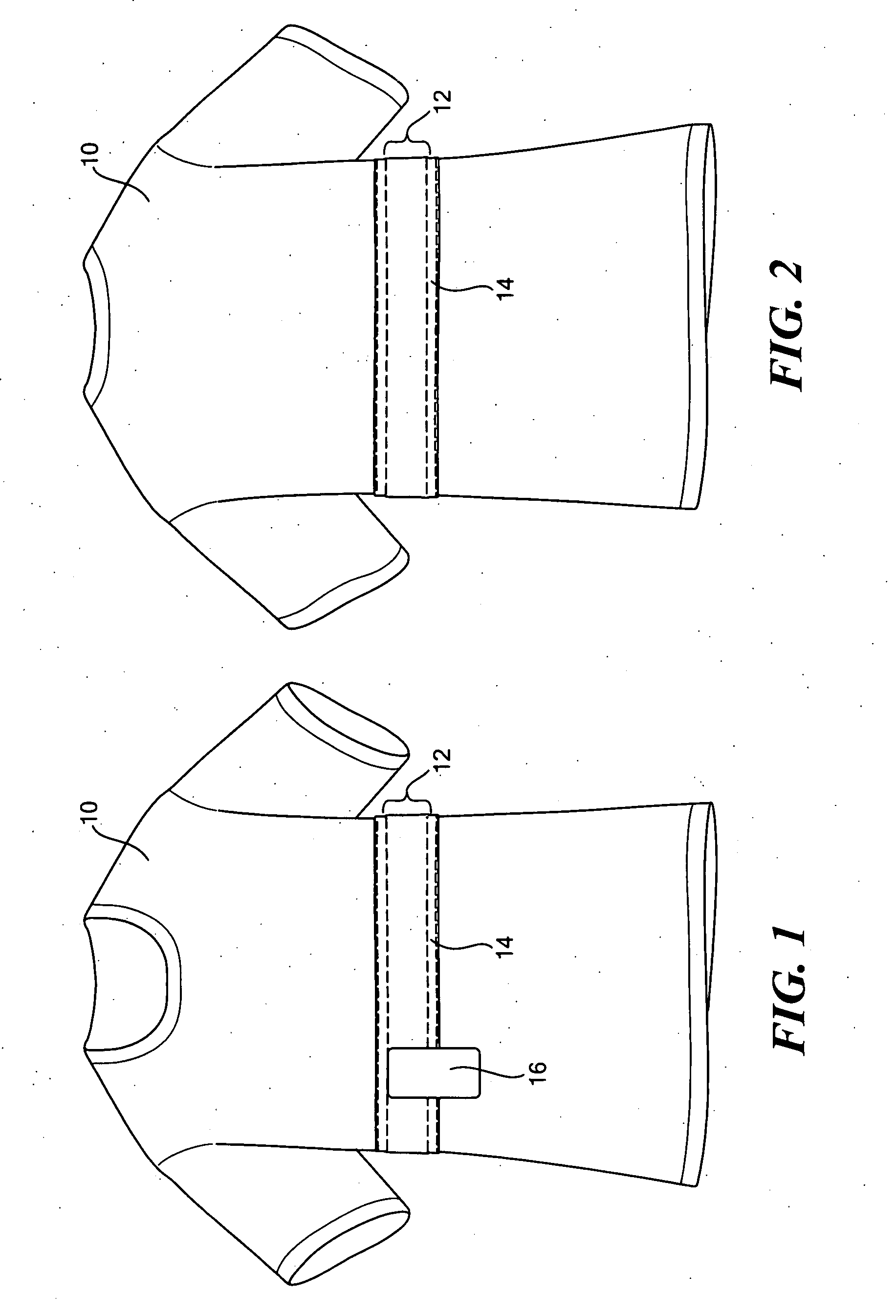
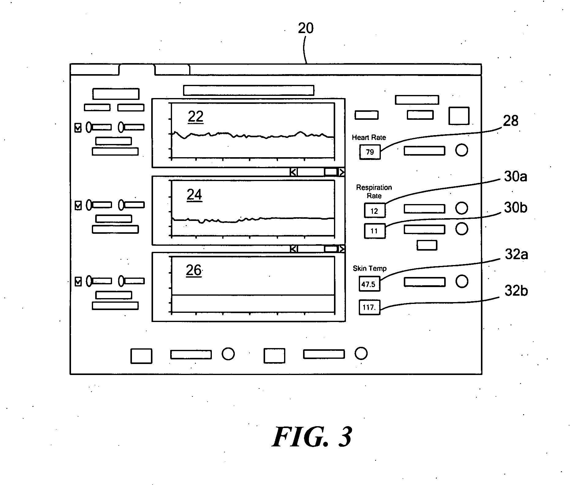
[0071]FIGS. 1-2 show one example of one version of a physiological status monitoring system in accordance with this invention. Easily washable garment or shirt 10 can be made of any fabric (e.g., cotton) but in this example is typically made of a “compression” fabric often including Lycra material (e.g., the POLARTEC® POW...


PUM


Abstract

A physiological status monitoring system includes a shirt and a stretchable circumferential band attached to the shirt. The stretchable band includes a respiration detector subsystem and signal transmission conductors. One or more sensors on the band are electrically connected to a signal transmission conductor. At least one sensor has an exposed electrode inside the shirt. The system includes a cover over the band and / or the one or more sensors. A connection subsystem on the band is electrically connected to the respiration detector subsystem and the signal transmission conductors and includes signal traces therefrom to a first connector accessible from outside the shirt. An electronics module is releasably attached to the shirt and includes a second connector which mates with the first connector. The electronics module includes a processing system and a transmitter. The remote display unit includes a receiver, a display, and a processing system.

Description

RELATED APPLICATIONS [0001] This application is a continuation-in-part application of U.S. patent application Ser. No. 10 / 922,336, filed Aug. 20, 2004, which is incorporated herein by reference.FIELD OF THE INVENTION [0002] The subject invention relates to a physiological monitoring system able to monitor and report a person's vital signs such as ECG, respiration, and the like. BACKGROUND OF THE INVENTION [0003] Different versions of physiological monitoring systems, some integrated to a certain extent in clothing, have been proposed. The idea is to be able to monitor the vital signs (e.g., heart rate, respiration rate, and the like) as a subject performs his, her, or its normal activities or duties. Such a system could be used by military personnel, fire fighters and police officers, athletes, patients, and animals. [0004] Vivometrics (see www.vivometrics.com) offers the “Life Shirt” as but one example of a physiological monitoring shirt-based system. See also, for example, U.S. Pa...

Claims


Application Information

Patent Timeline
IPC IPC(8): A61B5/00
CPCA61B5/0002A61B5/02055A61B5/0245A61B2562/227A61B5/0816A61B5/6805A61B2560/045A61B5/0806
Inventor FARRELL, BRIANSTREETER, RICHARDBOWMAN, JEREMYMCDONALD, DAVIDNAHASS, PAUL
Owner FOSTER-MILLER
Learn More