Offset tool guide for femoral head preparation

Inactive Publication Date: 2007-12-27
HOWMEDICA OSTEONICS CORP
View PDF18 Cites 84 Cited by
  • Summary
  • Abstract
  • Description
  • Claims
  • Application Information

AI Technical Summary

Benefits of technology

[0011]An object of the present invention is to more accurately position the preparatory reshaping of a femoral head in preparation for a hip resu

Problems solved by technology

The satisfactory performance of these implants can be affected not only by the design of the component itself, but also by the surgical positioning of the implanted component and the long-term fixation of the implant.
Improper placement or positioning of the implant can adversely affect the goal of satisfactorily restoring the clinical bio-mechanics of the joint as well as impairing adequate fixation of the component when implanted.
These stem type prostheses are very successful but when they fail the stem can create considerable damage inside the bone.
The implant can move about inside the bone causing the intramedullary cavity to be damaged.
Because a stiff stem transmits the forces more directly into the femoral shaft, such implants have the further disadvantage that they can weaken the surrounding bone proximal to the hip joint due to stress shielding.
Prior art designs often require the entire implant to be replaced even if only a portion of the implant fails.
This is often due to the implant suffering

Method used


Image

  • Offset tool guide for femoral head preparation
  • Offset tool guide for femoral head preparation
  • Offset tool guide for femoral head preparation

Examples


Embodiment Construction

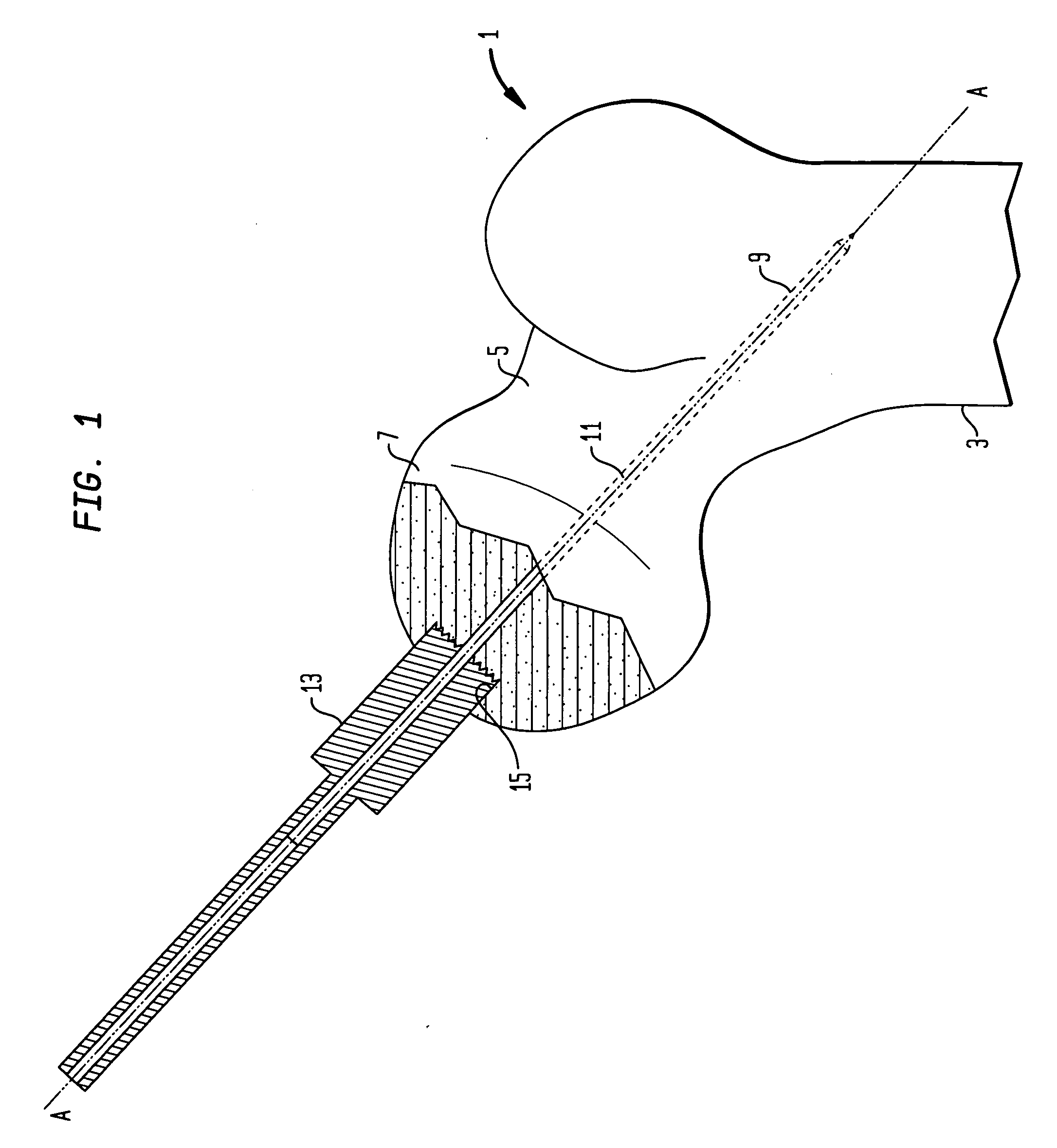
[0032]FIGS. 1-13 show an embodiment of the apparatus and method of the present invention to enable an accurately positioned preparation of a femoral head for installation of a hip surfacing implant.

[0033]FIG. 1 shows a femur 1 with an upper portion of the proximal femur 3, a femoral neck 5, and a femoral head 7. Based on pre-operative planning, imaging and measurements in situ, an initial guide wire 11, has been placed in the femoral neck 5. The guide wire 11 is impacted or inserted into the femoral head 7 toward the axis of the femoral shaft 3 creating a guide wire bore 9. The guide wire bore 9 and guide wire 11 have a central axis A-A. Coaxial with the axis A-A, the guide wire bore 9 and guide wire 11, is a guide post counterbore 15 located centrally on the femoral head 7. The guide post counterbore 15 is created by the guide post reamer 13. The guide post reamer 13 is cannulated to fit over the guide wire 11 and is capable of rotation about the guide wire. The guide post reamer 1...


PUM


Abstract

A surgical offset guide tool for making a subsequent preparation on an outer surface of a natural femoral head following a first oversize preparation is disclosed. The guide tool guides a rotary cutter about an offset axis of revolution, the axis being offset from a datum having an axis coaxial with an initial axis of revolution used to create the first oversize preparation of the femoral head. Methods of using the offset guide tool and kits including the offset guide tool are disclosed.

Description

BACKGROUND OF THE INVENTION[0001]The present invention relates to systems, kits and methods for joint replacement requiring preparation of the femoral head. More particularly, the present invention includes tools and methods to correctly position preparation tooling to establish the surgical positioning of an implant for a femoral head.[0002]Artificial joint prostheses are widely used today, restoring joint mobility to patients affected by a variety of conditions, including degeneration of the joint and bone structure. Typically, the failed bone structure is replaced with an orthopedic implant that mimics, as closely as possible, the structure of the natural bone and performs its functions. The satisfactory performance of these implants can be affected not only by the design of the component itself, but also by the surgical positioning of the implanted component and the long-term fixation of the implant. Improper placement or positioning of the implant can adversely affect the goal ...

Claims


Application Information

Patent Timeline
IPC IPC(8): A61B17/15A61B17/00
CPCA61B17/1637A61B17/175A61B17/1668
Inventor TULKIS, PETER
Owner HOWMEDICA OSTEONICS CORP
Why Eureka
Try Eureka