Water Stopping Structure and Water Stopping Method
- Summary
- Abstract
- Description
- Claims
- Application Information
AI Technical Summary
Benefits of technology
Problems solved by technology
Method used
Image

Examples
first embodiment
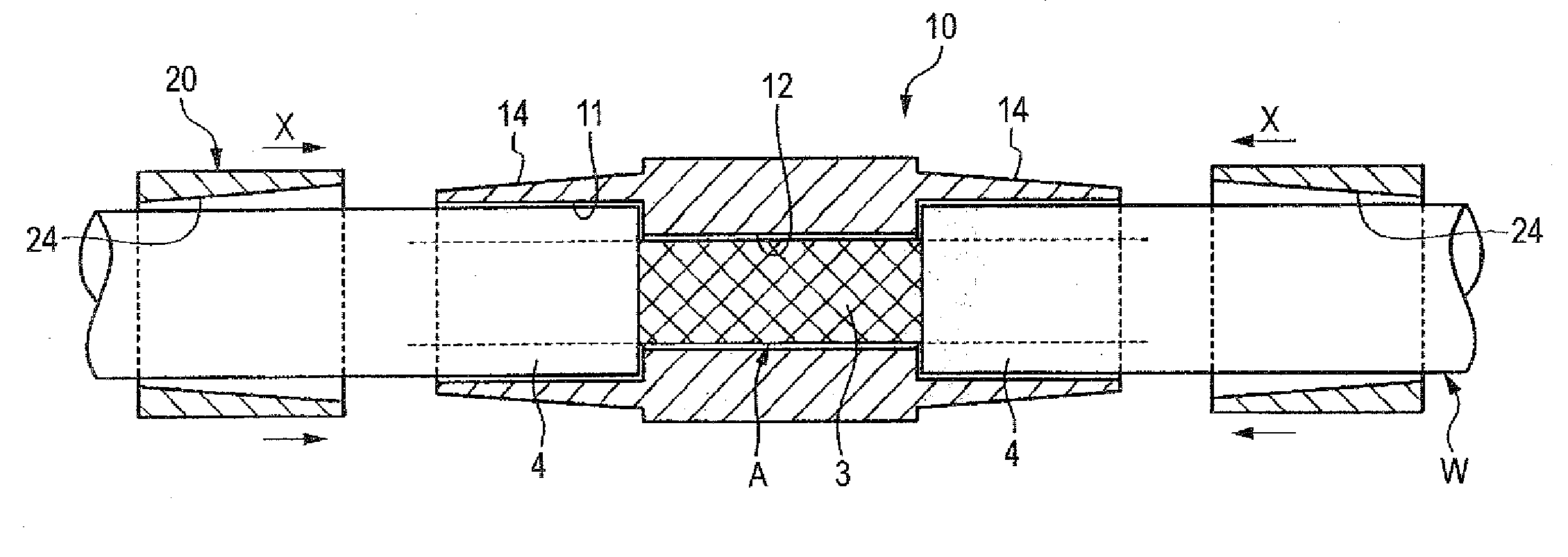
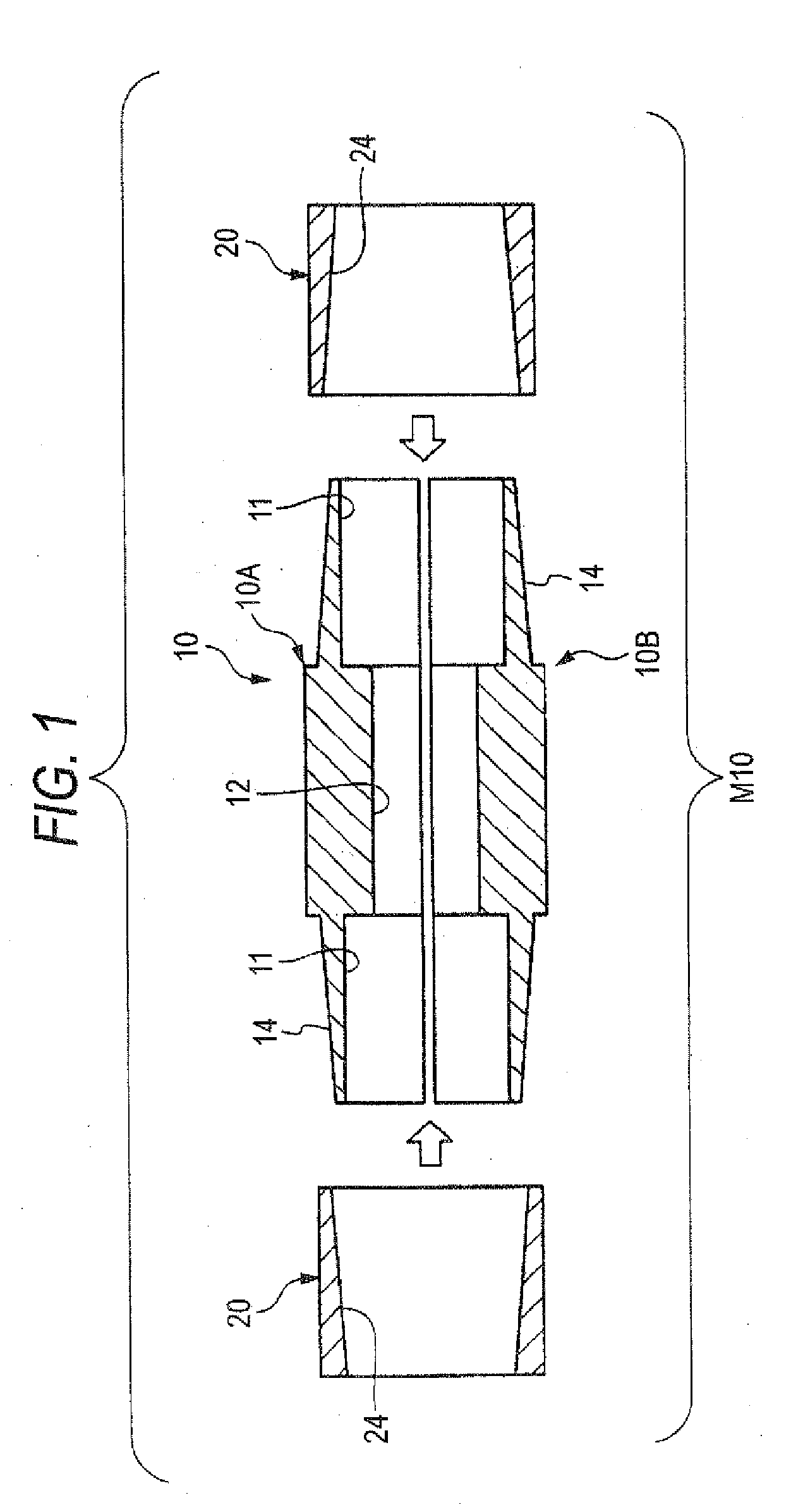
[0037]FIG. 1 is a sectional view showing a constitution of a water stopping structure M120 of a first embodiment, FIG. 2 is an explanatory view of a skin peeling step as a step before mounting the water stopping structure M10, FIG. 3 is an explanatory view of a next step of supplying an adhering agent, FIG. 4 is an explanatory view showing a state of mounting the water stopping member M10, FIG. 5 is a sectional view of a finished water stopping structure.
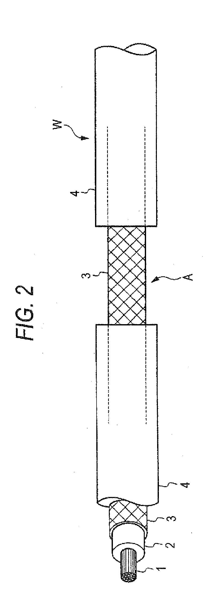
[0038]As shown by, for example, FIG. 2, a shielded wire W constituting an object of using the water stopping structure M10 is arranged with a core 1, an insulating member 2, a shielded member 3 of a knit structure or the like, and a sheath 4 constituting an outer skin successively from an inner side to an outer side.
[0039]As shown by FIG. 2 through FIG. 5, a middle of the sheath 4 of the shielded wire W is peeled, an adhering agent S is permeated to the disposed shielded member 3, thereafter, the water stopping member M10 is mounted...
second embodiment
[0052]FIG. 6 is a sectional view of a water stopping structure M110 of a second embodiment of the invention.
[0053]The water stopping structure M110 is constructed by a constitution the same as that of the water stopping structure M10 of the first embodiment except that a drain hole 16 is formed at a peripheral wall of a water stopping member 110 to be communicated with the hollow portion 12. The water drain hole 16 is constituted by a ring-like groove 16a formed at an inner peripheral wall of the hollow portion 12, and a through hole 16b bored in a radius direction to be communicated with the ring-like groove 16a. Also in a case of using the water stopping structure M110, the water stopping structure MA110 as shown by FIG. 7 is provided after having been processed by steps similar to those of the first embodiment.
[0054]When the drain hole 16 is formed at the peripheral wall of the water stopping member 110 in this way, even in a case in which water F invades by spreading through the...
third embodiment
[0057]FIG. 9 is a sectional view of a water stopping structure MA210 realized by using a water stopping structure M210 according to a third embodiment of the invention.
[0058]The water stopping structure M210 is provided with screw mechanism (fastening member) comprising a male screw 212 and a female screw 222 for sliding a fastening ring 220 in a direction of producing a wedge action between the fastening ring 220 and a water stopping member 220.
[0059]Here, a large diameter portion 221 is provided at an end portion of the fastening ring 220, the female screw 222 is provided at an inner periphery thereof, on the other hand, the male screw 212 to be screwed with the female screw 222 is provided at an outer periphery of an end portion of the water stopping member 210. Other constitution is the same as that of the first embodiment.
[0060]In this way, by providing the screw mechanism comprising the female screw 222 and the male screw 212 between the water stopping member 210 and the faste...
PUM
 Abstract
Description
Claims
Application Information
 - Generate Ideas
- Intellectual Property
- Life Sciences
- Materials
- Tech Scout
- Unparalleled Data Quality
- Higher Quality Content
- 60% Fewer Hallucinations
Browse by: Latest US Patents, China's latest patents, Technical Efficacy Thesaurus, Application Domain, Technology Topic, Popular Technical Reports.
© 2025 PatSnap. All rights reserved.Legal|Privacy policy|Modern Slavery Act Transparency Statement|Sitemap|About US| Contact US: help@patsnap.com