
Ultrasonic Solution Separating Method and Ultrasonic Separating Apparatus Used In Such Method

a technology of ultrasonic vibrators and separators, which is applied in the direction of separation processes, other chemical processes, and distillation by vibration, etc., can solve the problems of not being able to efficiently atomize the amount of solution corresponding to the number of ultrasonic vibrators, and not being able to efficiently atomize the amount of solution into mist, so as to achieve efficient atomization, reduce the amount of carrier gas, and be atomized efficiently

Inactive Publication Date: 2008-01-03
ULTRASOUND BREWERY
View PDF2 Cites 29 Cited by
  • Summary
  • Abstract
  • Description
  • Claims
  • Application Information

AI Technical Summary

Benefits of technology

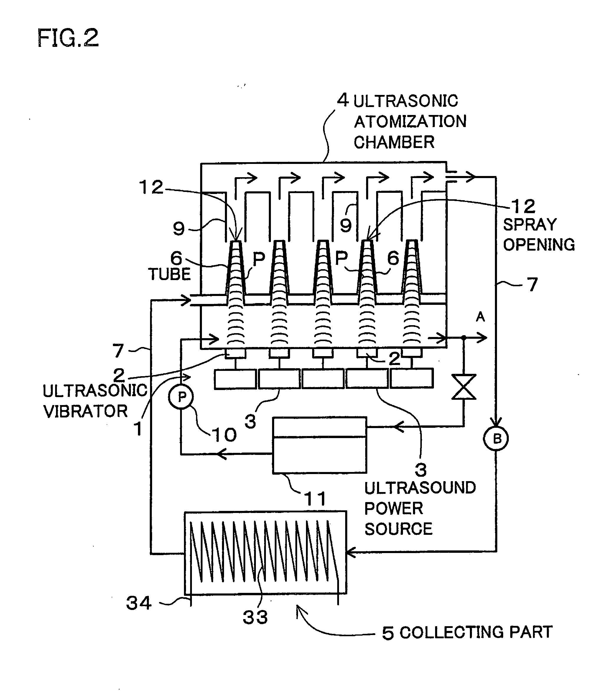
[0007] A first object of the invention is to achieve such a goal, that is, to provide an ultrasonic solution separation method and apparatus for atomizing a solution into mists efficiently by a plurality of ultrasonic vibrators, with a reduced amount of carrier gas.
[0068] The ultrasonic atomization chamber 4, 304, 404, 804, 904 and the collection unit 5, 305, 405, 805, 905 are preferably filled with an inactive gas. In this apparatus, the inactive gas prevents a deterioration of the solution in the ultrasonic atomization chamber 4, 304, 404, 804, 904 and the collection unit 5, 305, 405, 805, 905. As such, it becomes possible to obtain a highly concentrated solution in a state of higher quality. INDUSTRIAL APPLICABILITY

Problems solved by technology

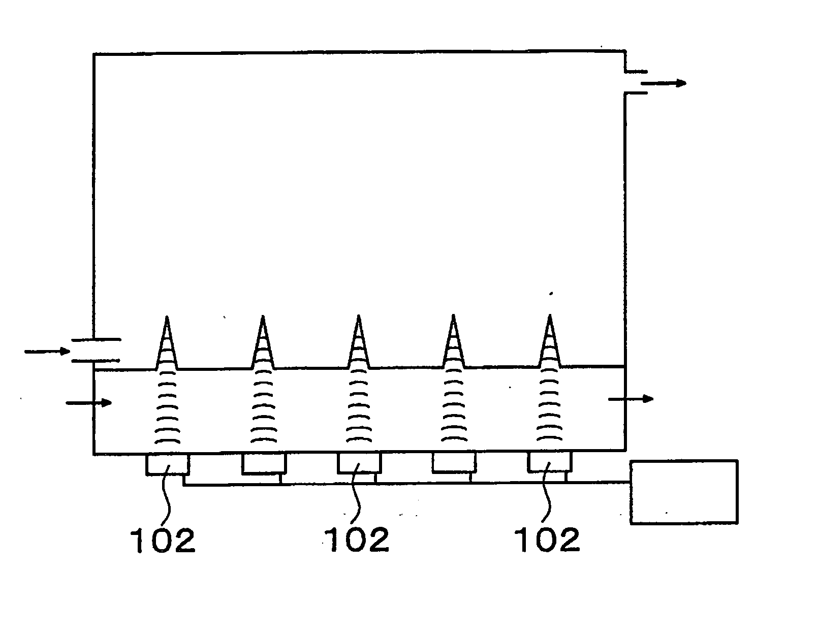
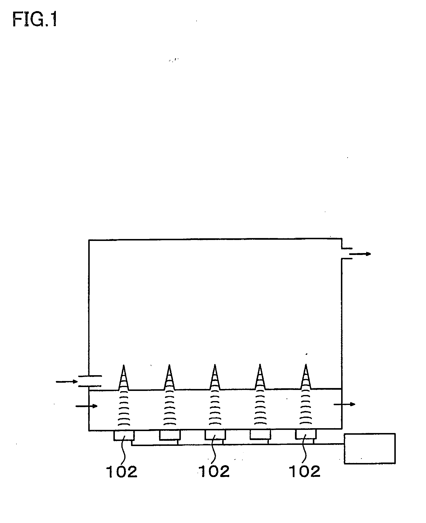
In this apparatus, however, it is not possible for all of the ultrasonic vibrators 102 to atomize a solution into mists efficiently at the same time.
Consequently, it becomes problematic that even when a lot of ultrasonic vibrators are provided, an amount of solution corresponding to the vibrator number cannot be atomized into mists.
However, when a greater amount of air is supplied, the atomized mists have to be condensed from such amount of air, resulting in a reduced efficient of recovery.

Method used


Image

  • Ultrasonic Solution Separating Method and Ultrasonic Separating Apparatus Used In Such Method
  • Ultrasonic Solution Separating Method and Ultrasonic Separating Apparatus Used In Such Method
  • Ultrasonic Solution Separating Method and Ultrasonic Separating Apparatus Used In Such Method

Examples


Embodiment Construction

[0017] Embodiments of the present invention will now be discussed in conjunction with the accompanying drawings. It should be noted here that the following embodiments are intended to be illustrative of a method and apparatus to embody the technical ideas of the invention, and the inventive method and apparatus are, in no way, limited to the method and apparatus described below.

[0018] Further, in the present disclosure, reference numerals corresponding to members shown in the embodiments are suffixed to members shown in the “CLAIMS” and “MEANS FOR SOLVING PROBLEMS” in order to facilitate appreciation of the claims. However, the members shown in the claims shall, in no way, be specified to those members shown in the embodiments.

[0019] The ultrasonic solution separating apparatus of the invention separates a specified solution of a high concentration from a solution containing at least two substances. Although the invention is not intended to specify a solvent and / or a solute of the...


PUM

PropertyMeasurementUnit
frequencyaaaaaaaaaa
concentrationaaaaaaaaaa
timeaaaaaaaaaa

Abstract

An ultrasonic solution separating method and apparatus separates a solution by ultrasonically vibrating the solution by using an ultrasonic vibrator to atomize the solution into mists, and such atomized mists are condensed and collected for separation from the solution. In the present method and apparatus, a tube 6, defining a spray opening 12 at an upper end of the tube, is filled with the solution; an ultrasonic vibration is applied to the solution inside the tube 6, toward the spray opening 12; the atomized mists are dispersed from the spray opening 12; and a carrier gas is supplied to the mists dispersed from the spray opening 12 so that the mists are atomized in the carrier gas.

Description

TECHNICAL FIELD [0001] This invention relates to a method and apparatus for separating a highly concentrated solution having a high concentration of a specific substance from a mixture containing two or more substances, or for separating a target substance contained in a solution, and particularly pertains to a method and apparatus for separating alcohol of an even higher concentration from an alcohol solution such as Sake and a Sake raw material, or a separating method and apparatus ideal for separating a target substance from gasoline. BACKGROUND ART [0002] The present inventors have earlier developed an apparatus for separating highly concentrated alcohol from alcohol (See Patent Document 1). [0003] Patent Document 1: Japanese Laid-Open Patent Publication No. 2001-314724 [0004] In this particular separating apparatus, an alcohol solution is filled in an ultrasonic atomization chamber of a closed structure, the alcohol solution in the ultrasonic atomization chamber is ultrasonical...

Claims


Application Information

Patent Timeline
Patent Type & Authority Applications(United States)
IPC IPC(8): B01D17/00B01J19/00
CPCB01D1/16B01D3/006B01D3/346B05B17/0615B05B1/14B05B7/066B05B17/0607B01D19/0078
Inventor MATSUURA, KAZUOMIYAMOTO, TOSHIAKI
Owner ULTRASOUND BREWERY
Learn More