
Method for the construction of a laminated compound

a technology of laminated compounds and construction methods, applied in the direction of additive manufacturing processes, manufacturing tools, electric/magnetic/electromagnetic heating, etc., can solve the problems of platform jamming against the container wall, requiring a large degree of technical complexity, and risk of precision loss

Active Publication Date: 2008-01-03
VOXELJET AG
View PDF1 Cites 108 Cited by
  • Summary
  • Abstract
  • Description
  • Claims
  • Application Information

AI Technical Summary

Problems solved by technology

Bigger components must be put together from several parts, at the risk of a loss of precision.
The provision of a construction container, which contains a building platform that can be lowered in a vertical direction, requires a large measure of technical complexity in the sealing of the container wall against the building platform, to prevent the uncontrolled flow-out of particle material through the gap between the edge of the building platform and the container wall, without running the risk that the platform gets jammed against the container wall due to the granular particle material.
A further disadvantage of the currently specified construction forms, with building platforms that can be lowered, lies in the continuous increase of the weight that has to be moved around on the building platform as the building process proceeds.
This leads to extreme pressure on the tracks and power unit.
Furthermore, a sealing problem develops between the edge of the work opening and the already hardened part of the artificial container wall at the completion of the previous layer, over which the particle material of the newly deposited layer extends.

Method used


Image

  • Method for the construction of a laminated compound
  • Method for the construction of a laminated compound
  • Method for the construction of a laminated compound

Examples


Embodiment Construction

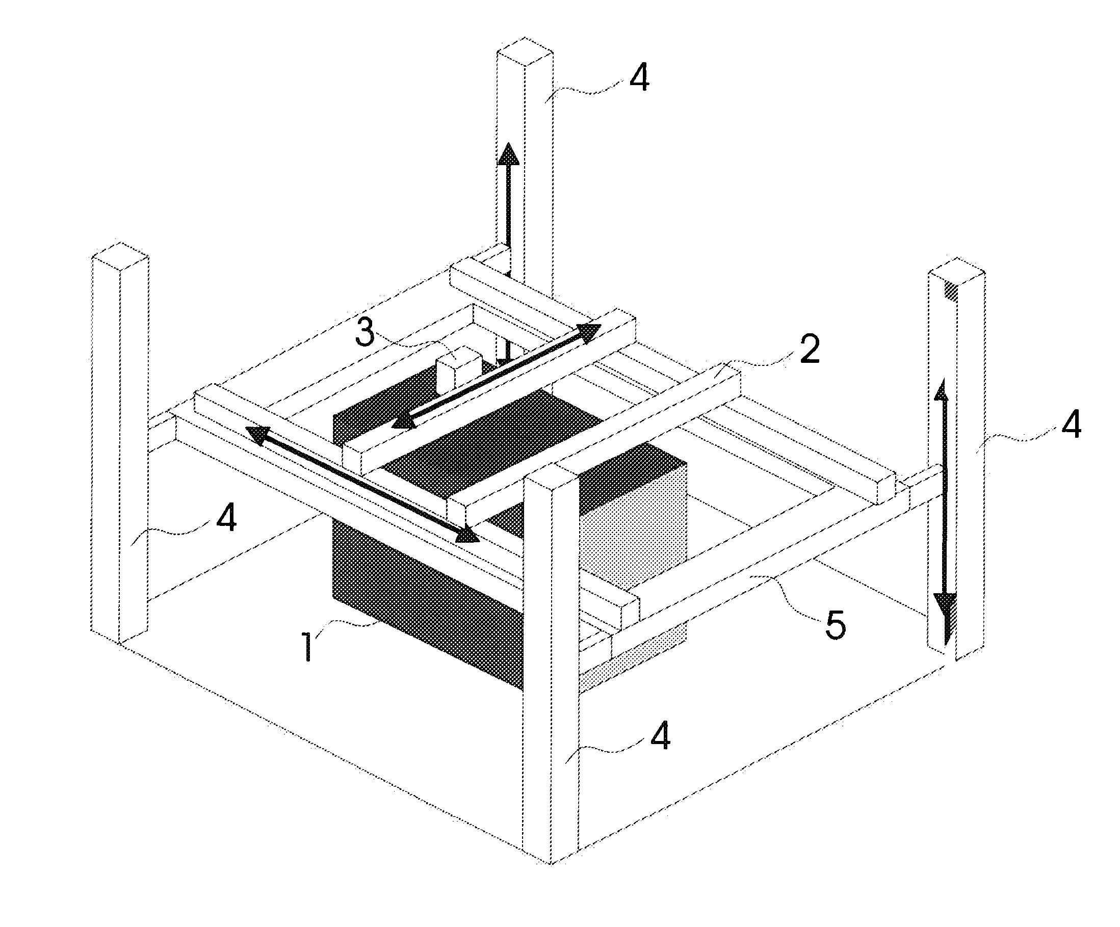
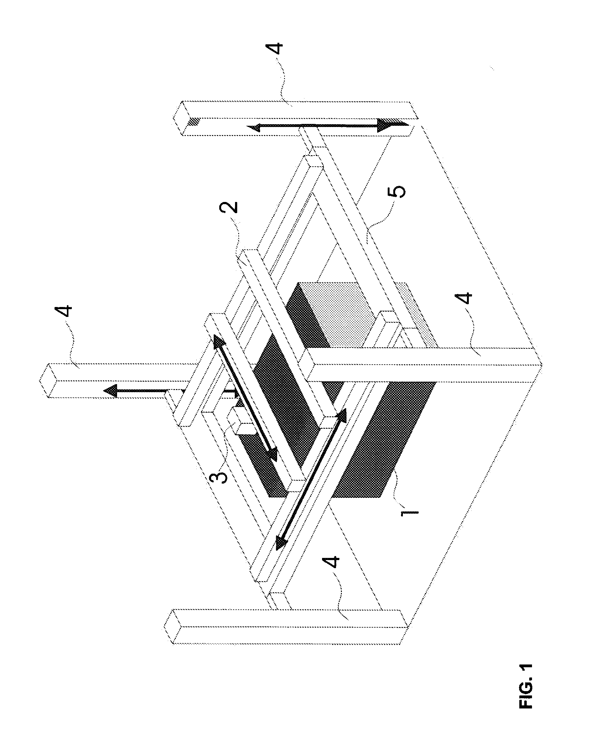
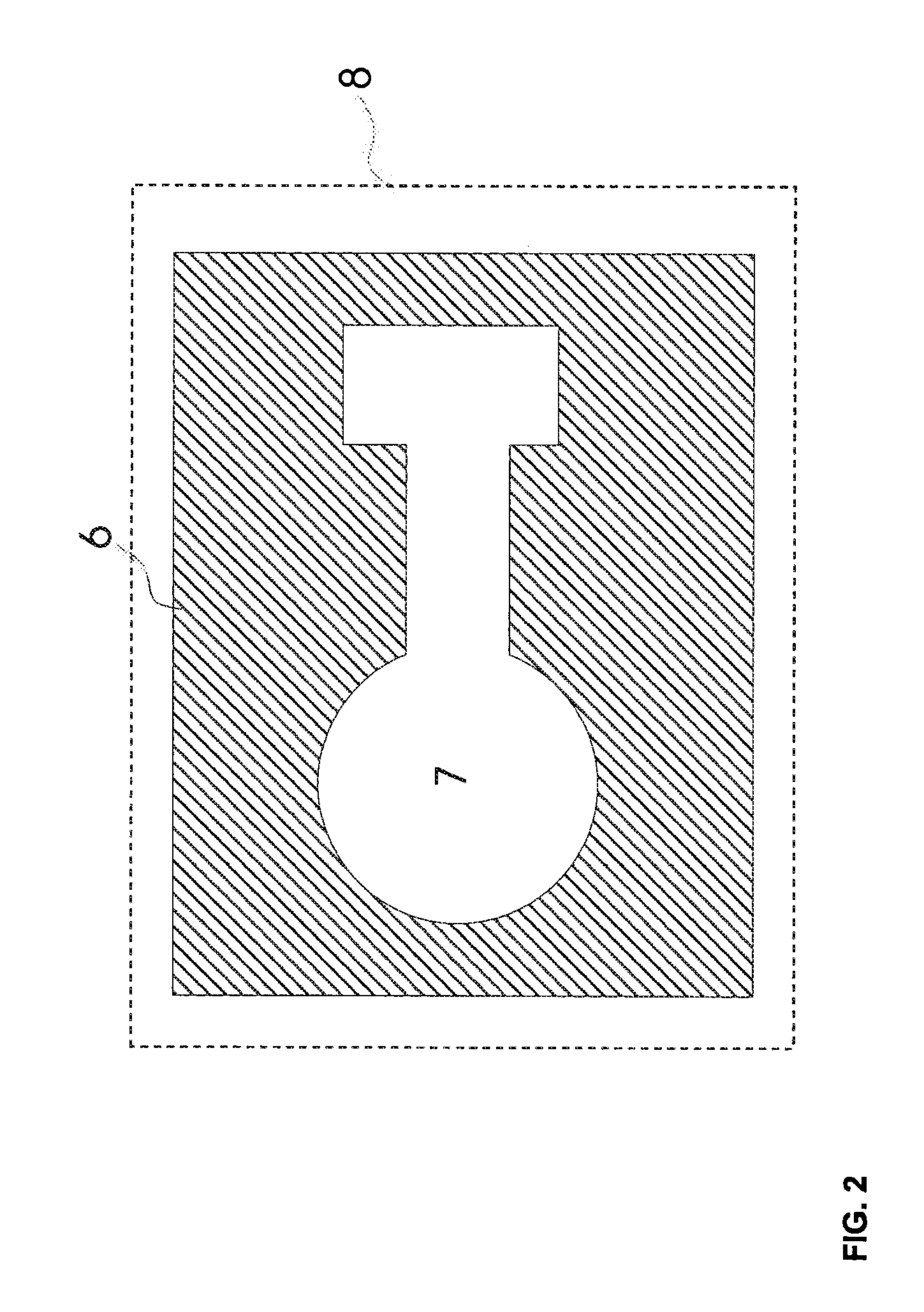
[0028] Through the invention the task is resolved to provide a method for the building of a laminated compound from a number of layers from particle material on top of one another, which for the formation of at least one mould 6 in predetermined onsite areas are hardened and joined to one another. With this process it should be possible to manufacture especially big and heavy moulds, with little loss of particle material relative to the size of the component, with flexible possibilities for the adjustment of the size of the working field.

[0029] Also with the method according to the invention, the layers are deposited in predetermined layer thickness one after the other on top of each other, through the depositing of the particle material from a dispensing device 2 during its movement above the working field, and selectively hardened in predetermined areas according to computer data. Contrary to the current state of technology, in the method according to the invention, the laminated...


PUM

PropertyMeasurementUnit
Thicknessaaaaaaaaaa
Thicknessaaaaaaaaaa
Thicknessaaaaaaaaaa

Abstract

A method or procedure for the construction of a laminated compound or mould made up of a number of layers of particle material on top of each other, which are hardened and joined to each other in predetermined onsite areas, which can differ from each other depending on position and expansion, so that from the predetermined hardened areas of the laminated compound at least one mould is formed. The layers are deposited individually one after another in predetermined layer thickness by the dispensing of particle material from a dispensing device during its movement above a working field and according to computer data in predetermined areas.

Description

CLAIM OF PRIORITY [0001] This application claims the benefit of the filing date German Patent Application 102006030350.4, filed on Jun. 30, 2006, hereby incorporated by reference for all purposes. FIELD OF THE INVENTION [0002] The invention concerns a method or procedure for the construction of a laminated compound made up of a number of layers of particle material on top of each other, which are hardened and joined to each other in predetermined onsite areas to manufacture a mould. BACKGROUND [0003] Objects can be created in a limited space with the assistance of generative methods according to computer data. For example, particle material can be deposited layer by layer through laser sintering on a building platform determined by the working field, and then by means of selectively applied laser radiation selectively hardened. The building platform is subsequently lowered and the procedure of applying another layer of particle material and subsequent hardening is repeated until the...

Claims


Application Information

Patent Timeline
IPC IPC(8): B29C41/02
CPCB22F3/1055B22F2998/00B29C67/0077B29C67/0081B22F3/003B29C64/153B29C64/165B33Y80/00B33Y10/00Y02P10/25B22F10/28B22F12/44B22F12/49B22F10/14B22F12/33B22F10/34B22F12/222B22F12/88B22F12/50B22F10/68B22F12/224B33Y50/02
Inventor EDERER, INGO
Owner VOXELJET AG
Learn More