
Fall detection device and magnetic disk drive

a detection device and magnetic disk technology, applied in the direction of acceleration measurement using interia force, acceleration measurement in multiple dimensions, instruments, etc., can solve the problems of complex and expensive circuits, complicated acceleration sensors and circuits using the same, etc., and achieve the effect of improving fall detection

Active Publication Date: 2008-01-03
MURATA MFG CO LTD
View PDF23 Cites 13 Cited by
  • Summary
  • Abstract
  • Description
  • Claims
  • Application Information

AI Technical Summary

Benefits of technology

The present invention provides a fall detection device that does not require detection of DC acceleration and improves fall detection. The device includes an acceleration sensor that outputs a signal in response to acceleration, a differentiator that differentiates the output signal, an integrator that integrates the output signal, and a state determination processor that determines whether the output signals exceed predetermined thresholds. The device can detect falls in all directions and can be used in a magnetic disk drive to protect it from damage caused by falls. The use of an acceleration sensor that can detect DC acceleration reduces the cost of the device. The integration of the output signals at the predetermined thresholds improves the responsiveness of fall detection and reduces the likelihood of false detection. The device can be used in a magnetic disk drive to protect it from damage caused by falls.

Problems solved by technology

Therefore, the acceleration sensor and a circuit using the same are complicated and expensive.
In either case, as will be described later, there are many detection errors, such as falsely detecting as a fall a change in the tilt of a mobile apparatus containing the fall detection device.
However, the above-described method of detecting DC acceleration theoretically requires three acceleration sensors and a circuit for processing sensor outputs, resulting in an expensive system.

Method used


Image

  • Fall detection device and magnetic disk drive
  • Fall detection device and magnetic disk drive
  • Fall detection device and magnetic disk drive

Examples


Embodiment Construction

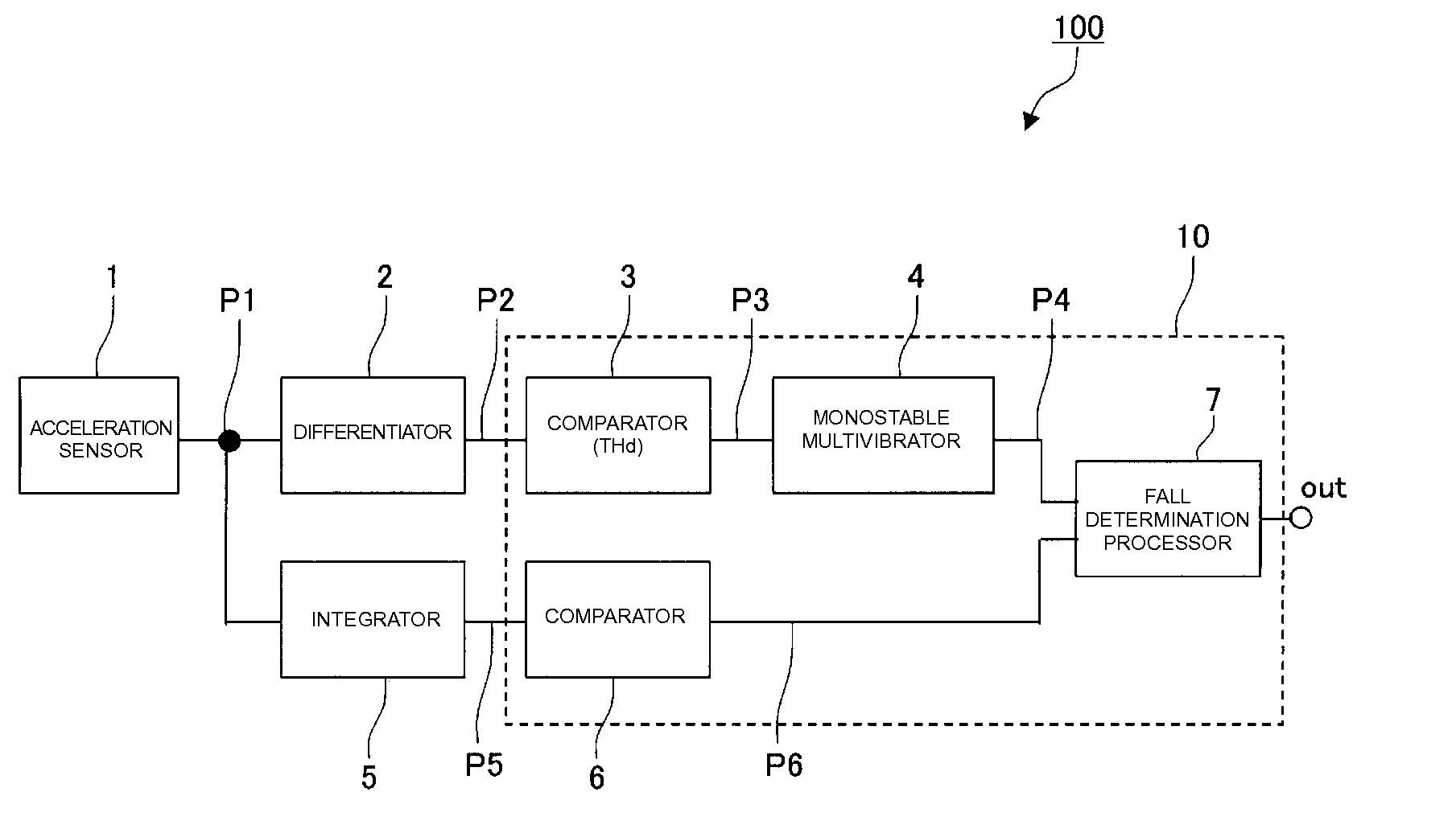
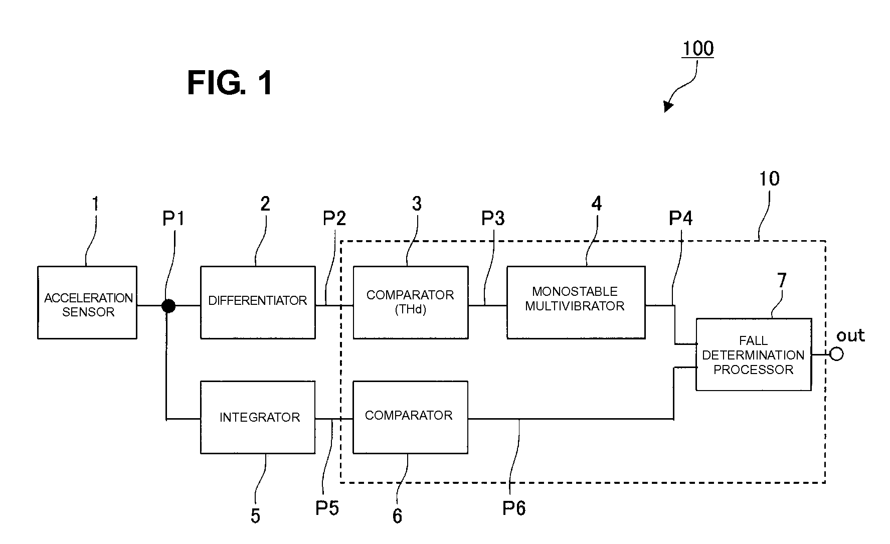
[0040] The structure of a fall detection device according to a first preferred embodiment of the present invention will be described with reference to FIGS. 1 to 7.

[0041]FIG. 1 is a block diagram of the structure of the fall detection device. An acceleration sensor 1 preferably is a piezoelectric acceleration sensor that generates a piezoelectric effect in response to stress according to acceleration. An output signal P1 of the acceleration sensor 1 is output as a voltage signal that is proportional to acceleration within a predetermined detectable range. Since the acceleration sensor 1 preferably is a piezoelectric acceleration sensor, the output signal P1 does not include a DC component or a very low frequency component signal. In other words, the acceleration sensor 1 does not detect DC acceleration.

[0042] A differentiator 2 is a circuit that differentiates the output signal P1 of the acceleration sensor 1 and outputs a differential signal P2. The differentiator 2 preferably in...


PUM

PropertyMeasurementUnit
frequencyaaaaaaaaaa
accelerationaaaaaaaaaa
thresholdaaaaaaaaaa

Abstract

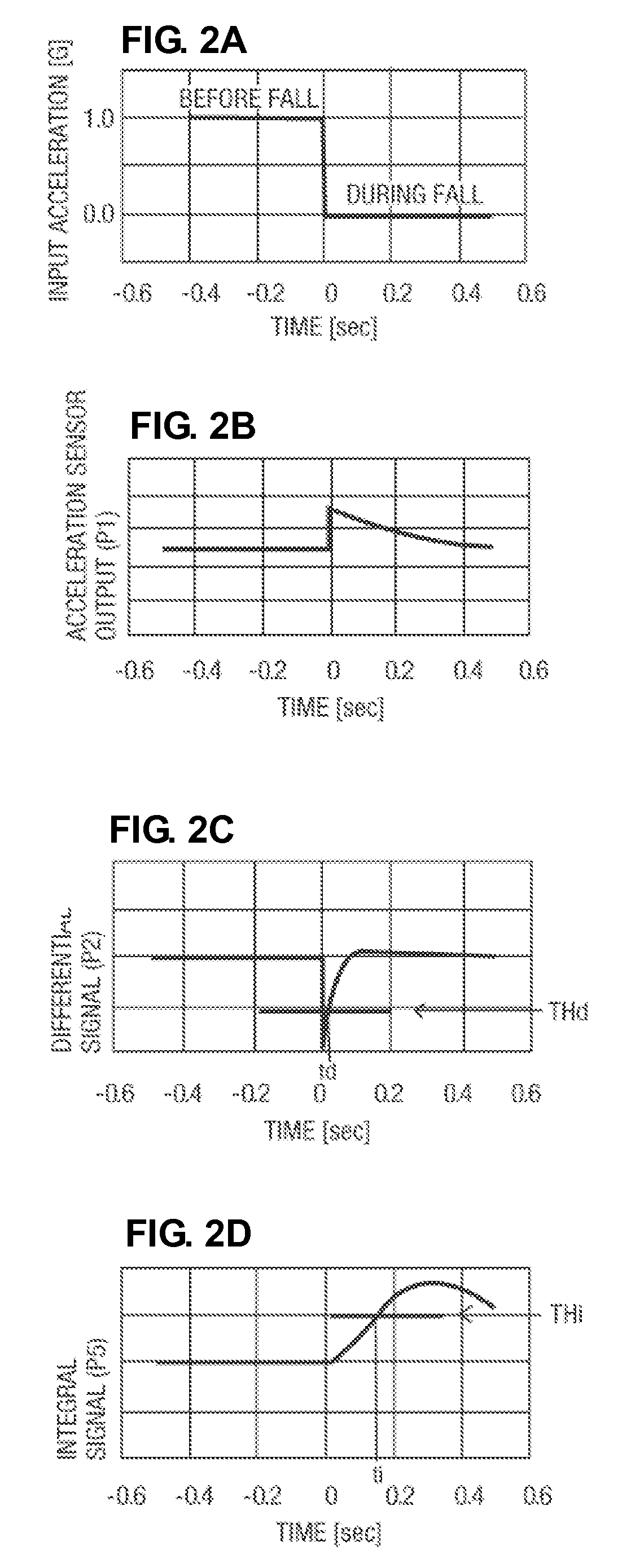
An acceleration sensor outputs a signal in accordance with acceleration. A differentiator outputs a differential signal of the output signal. A comparator inverts the state of an output when the differential signal goes beyond a threshold. A monostable multivibrator maintains the state-inverted signal of the output for a predetermined period of time. An integrator integrates the acceleration detection signal. A comparator inverts the state of an output signal when an integrated signal goes beyond a threshold. A fall determination processor outputs a signal out indicating that a fall has been detected in a situation in which, when the output of the monostable multivibrator is active, the state of the output of the comparator is inverted.

Description

BACKGROUND OF THE INVENTION [0001] 1. Field of the Invention [0002] The present invention relates to a fall detection device for detecting whether a device is falling or not on the basis of acceleration, and a magnetic disk drive including the same. [0003] 2. Description of the Related Art [0004] Devices for detecting whether a device is falling or not are disclosed in Japanese Unexamined Patent Application Publication No. 2000-241442 (Patent Document 1), Japanese Unexamined Patent Application Publication No. 08-221886 (Patent Document 2), and Japanese Unexamined Patent Application Publication No. 2000-298136 (Patent Document 3). [0005] A fall detection device described in Patent Document 1 detects whether the device is falling based on whether a differential output signal of a detection signal of an acceleration sensor is substantially 0. [0006] A device described in Patent Document 2 obtains a speed signal by integrating an output signal of an acceleration sensor once and, when th...

Claims


Application Information

Patent Timeline
Patent Type & Authority Applications(United States)
IPC IPC(8): G01R27/00G01P15/00G11B19/04G11B21/12
CPCG01P15/0891G11B19/04G01P15/18G01P15/09G01P15/00G11B21/12
Inventor HORIGUCHI, CHIKAHIROTABOTA, JUN
Owner MURATA MFG CO LTD
Learn More