Delay-locked loop apparatus adjusting internal clock signal in synchronization with external clock signal

a loop apparatus and clock signal technology, applied in the field of delay-locked loop apparatus, can solve the problems of jitter, unnecessary current consumption, skew between the external clock and the generated internal clock, etc., and achieve the effect of reducing the generated errors and increasing the pulse width

Inactive Publication Date: 2008-01-03
SK HYNIX INC
View PDF5 Cites 20 Cited by
  • Summary
  • Abstract
  • Description
  • Claims
  • Application Information

AI Technical Summary

Benefits of technology

[0017]Accordingly, the present invention has been made to solve the above and other problems occurring in the prior art. The present invention reduces errors generated by the phase difference detection in a DLL circuit through increasing the pulse widths of clocks used for the phase difference detection when the widths of the high pulses of the clocks are short.

Problems solved by technology

That is, when an externally inputted clock is used in a semiconductor memory device, a skew may occur between the external clock and the generated internal clock or between the external clock and the data signal.
Therefore, a DLL apparatus constructed as shown in FIG. 1 includes a circuit (i.e., the second replica delay unit 130) that is unnecessary after a duty cycle compensation operation begins, thereby causing unnecessary current consumption.
When the first and second phase detectors 120 and 140 incorrectly detect a phase difference, the rising clock “PCLK” and falling clock “FCLK” may be incorrectly locked, or jitter may increase due to an error in phase detection despite the locked state of these clocks.

Method used


Image

  • Delay-locked loop apparatus adjusting internal clock signal in synchronization with external clock signal
  • Delay-locked loop apparatus adjusting internal clock signal in synchronization with external clock signal
  • Delay-locked loop apparatus adjusting internal clock signal in synchronization with external clock signal

Examples


Embodiment Construction

[0033]Hereinafter, a preferred embodiment of the present invention will be described with reference to the accompanying drawings. In the following description and drawings, the same reference numerals are used throughout to designate the same or similar components; therefore, repetition of the description of such same or similar components will be omitted.

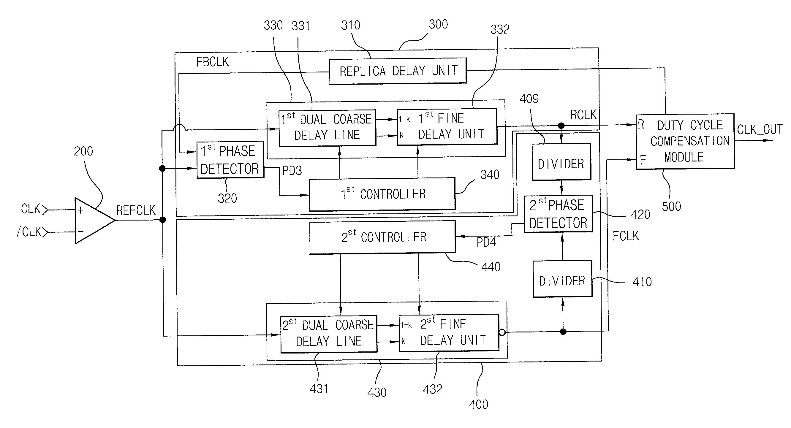
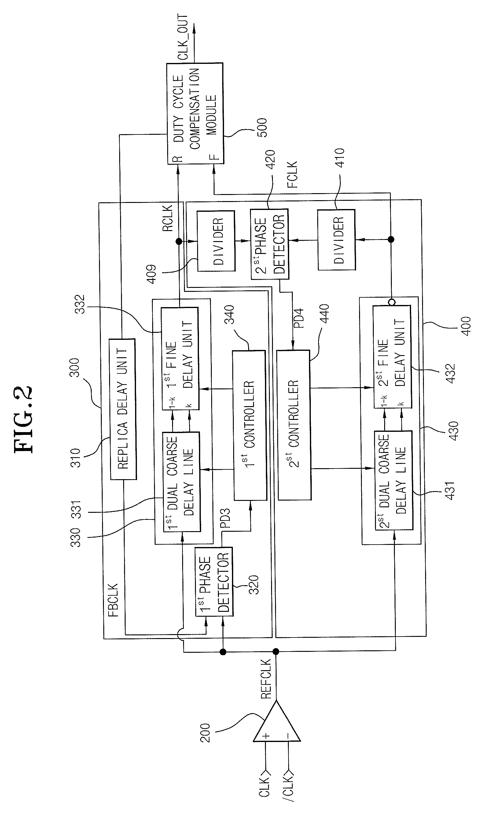
[0034]The construction of a delay-locked loop apparatus according to an embodiment of the present invention is shown in FIG. 2. It is noted that “clock signal” is also referred to as “clock” in this disclosure. According to an embodiment of the present invention, a reference clock “REFCLK” and a feedback clock “FBCLK” obtained by replica-delaying the reference clock “REFCLK” are compared to each other, and a delay locking operation for a rising clock “RCLK” is performed. Upon completion of the delay locking operation for the rising clock “RCLK,” an inverted clock obtained by inverting the reference clock “REFCLK” and the rising clo...


PUM


Abstract

A delay-locked loop apparatus includes at least a rising-clock delay-locked circuit, a falling-clock delay-locked circuit, and a duty cycle compensation circuit. The rising-clock delay-locked circuit detects the phase difference between a first clock inputted as a reference clock and a second clock obtained by replica-delaying the first clock, and then delay-locks the first clock and outputs a rising clock. The falling-clock delay-locked circuit detects the phase difference between an inverted clock of the first clock and the rising clock after a delay locking operation with respect to the rising clock, delay-locks an inverted clock of the first clock and outputs a falling clock. The duty cycle compensation circuit compensates duty cycles of the delay-locked rising clock and falling clock, and the falling-clock delay-locked circuit includes a divider for separately dividing the inverted clock and the delay-locked rising clock.

Description

CROSS-REFERENCE TO RELATED APPLICATIONS[0001]The present application claims priority to Korean patent application number 10-2006-0061544 filed on Jun. 30, 2006, which is incorporated herein by reference in its entirety.BACKGROUND OF THE INVENTION[0002]The present invention relates to a delay-locked loop apparatus, and more particularly to a delay-locked loop apparatus that is applied to a synchronous memory device and adjusts the delay of an internal clock signal such that the internal clock signal is synchronized with an external clock signal.[0003]As generally known in the art, a delay-locked loop (DLL) apparatus is used to delay an internal clock of a synchronous memory device using clocks such that the internal clock can be synchronized with an external clock without error (i.e., “skew”). It is noted that “clock signal” is also referred to as “clock” in this disclosure. That is, when an externally inputted clock is used in a semiconductor memory device, a skew may occur between ...

Claims


Application Information

Patent Timeline
Patent Type & Authority Applications(United States)
IPC IPC(8): H03L7/00
CPCH03L7/0812H03L7/0818H03L7/087H03L7/0816H03L7/081G11C11/407
Inventor YUN, WON JOOLEE, HYUN WOO
Owner SK HYNIX INC
Why Eureka
Try Eureka