Stereo Camera

Inactive Publication Date: 2008-01-03
HITACHI LTD
View PDF10 Cites 46 Cited by
  • Summary
  • Abstract
  • Description
  • Claims
  • Application Information

AI Technical Summary

Benefits of technology

[0006] The invention is characterized in that imaging element mount surfaces, to which left and right imaging elements are mounted, are provided on a stay and the left and right imaging elements are directly positioned on the stay to constitute a stereo camera. Thereby, accumulation of tolerances among parts is decreased and the positional relationship between imaging elements is improved in mount accuracy.

Problems solved by technology

Therefore, there is generated a need of decreasing such disagreement through an improvement in machining accuracy of a mount surface and assembly accuracy, so that stereo cameras involve problem of worsening in productivity and increase in cost.

Method used


Image

  • Stereo Camera
  • Stereo Camera
  • Stereo Camera

Examples


Embodiment Construction

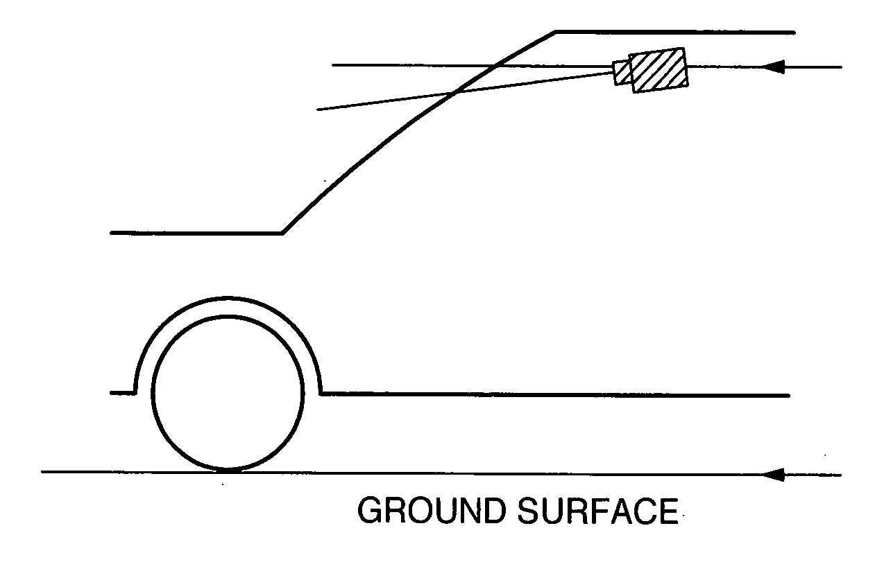
[0029] First, importance in the relative, positional relationship between left and right imaging elements in a stereo camera will be described. Generally, it is demanded in a stereo camera device that as an object is positioned distant, any disagreement except the parallax described above be absent. The principle of a stereo camera device is shown in FIG. 16(a). Here, δ denotes parallax, Z a measurement distance, f a focal distance, and b a base line length, among which the relationship shown by the following formula is established.

Z=b·f / δ  (formula 1)

[0030] When a pair of imaging means are mounted in the vicinity of a room mirror in a compartment in an orientation, in which photographing is effected in a vehicle traveling direction, as shown in FIG. 17 with a view to use in, for example, a car-mounted environment, pictures photographed by two imaging means disposed distant the base line length b from each other gives ones, which are obtained by photographing the same object at so...


PUM


Abstract

According to a conventional technique, first, the positional relation between a lens and an imaging element is kept at each of left and right camera units, adjustment is made so as to eliminate the rotation-direction deviation of an imaging element from one surface of a member to which a lens and an imaging element are to be attached before fixing, and then that camera unit is attached to a reference member to thereby constitute a stereo camera. However, although this method can eliminate a mounting position deviation when left and right camera units only are taken into consideration, a problem is posed that deviation again occurs due to poor machining precision and assembly precision at the mounting surface between a camera unit and a member when a camera unit is mounted to a stay. According to this invention, mounting surfaces for mounting left and right imaging elements to a stay are provided to directly position left and right imaging elements to the stay, whereby built-up tolerance between components is reduced and the positional mounting precision between imaging elements is improved.

Description

TECHNICAL FIELD [0001] The present invention relates to a stereo camera, on which a plurality of imaging elements is mounted. BACKGROUND ART [0002] A stereo camera, in which a pair of pictures photographed by the use of two imaging means is used for calculating a distance to an object to thereby recognize the object, begins to be applied to a car-mounted system for supporting a safe traveling of a vehicle and a monitor system for detecting entrance of a suspicious person and abnormality. [0003] In a stereo picture processing used in such systems, a triangulation technique is applied to a pair of photographed pictures spaced in position and photographed to find a distance, and a device for realization of such application generally comprises a pair of imaging means and a stereo picture processing LSI, which performs a triangulation picture processing on a pair of photographed pictures output from the imaging means. At this time, the stereo picture processing LSI performs processing to...

Claims


Application Information

Patent Timeline
IPC IPC(8): B60Q1/00H04N13/239
CPCB60R11/04B60R2011/0003G01S11/12H04N13/0239G03B35/08H04N5/2253G03B11/04G03B11/045H04N13/239H04N23/54
Inventor OHSUMI, KENFUKUHARA, MASAAKIMONJI, TATSUHIKOKOIKE, NORIO
Owner HITACHI LTD
Why Eureka
Try Eureka