Hydrogen injection apparatus

Active Publication Date: 2017-08-24
HONDA MOTOR CO LTD
View PDF1 Cites 0 Cited by
  • Summary
  • Abstract
  • Description
  • Claims
  • Application Information

AI Technical Summary

Benefits of technology

The present invention relates to a hydrogen injection apparatus that can reduce noises and size, and improve mounting accuracy to the body. A rigid mounting member is provided on the outer circumferential side of the injector, which is attached to the injector using a step or support base on the body. This results in a higher mounting accuracy compared to conventional fuel gas supply apparatus. Compared to using a resin mounting member, the present invention maintains strength and reduces size.

Problems solved by technology

However, for example, in the case where the sound proof member is made of metal, there is a concern that noises may be generated by the contact between the metal sound proof member and the metal support base, and the contact surface of the support base may be damaged or destroyed due to vibrations generated during operation of the injector.
In the case where the sound proof member is made of resin, there is a concern that the mounting accuracy may not be good or may not be stable because the rigidity of the resin sound proof member is insufficient in comparison with the metal sound proof member.
Further, the resin sound proof member needs to have a large size to compensate for the insufficient rigidity.

Method used


Image

  • Hydrogen injection apparatus
  • Hydrogen injection apparatus
  • Hydrogen injection apparatus

Examples


Embodiment Construction

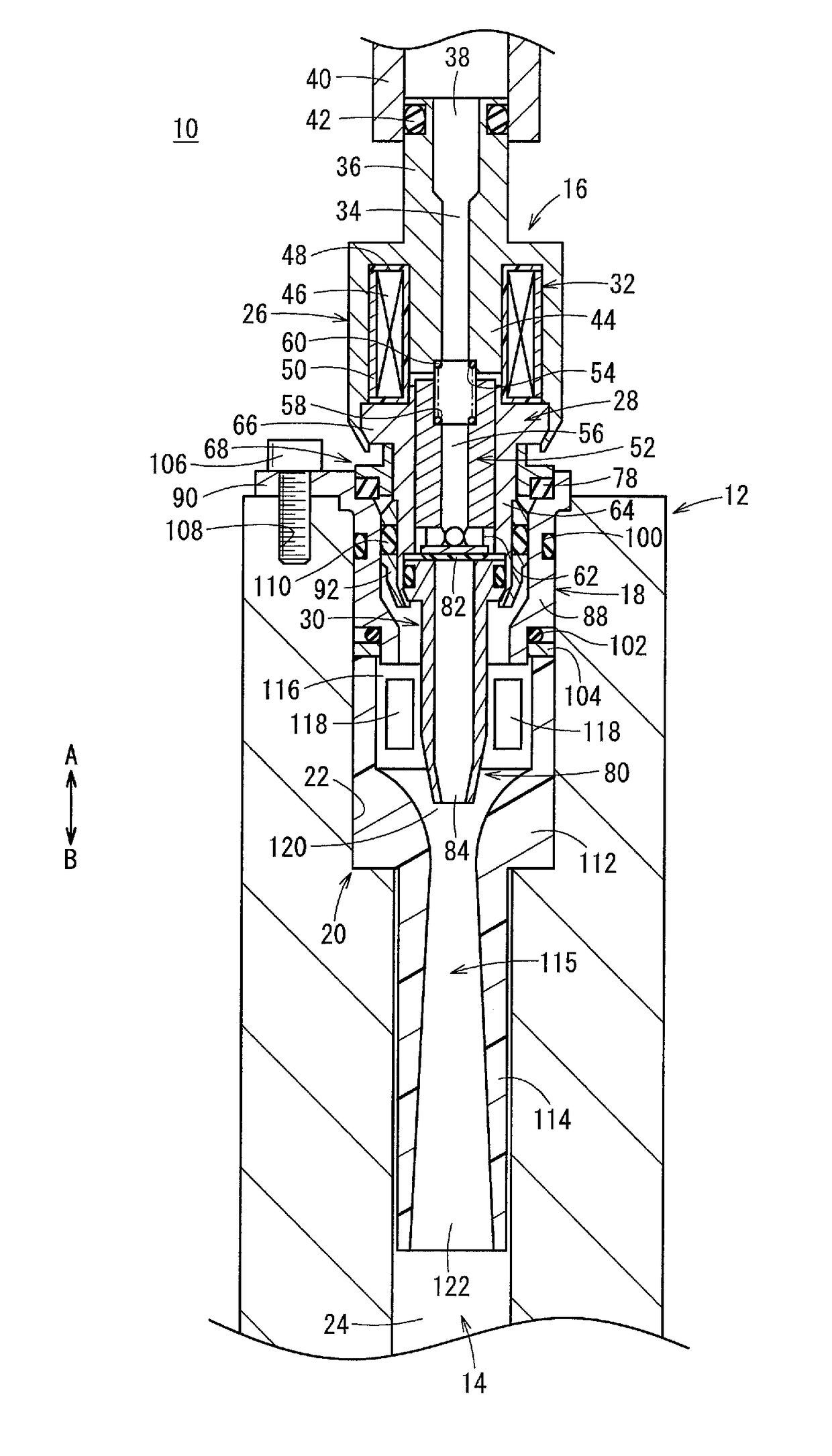
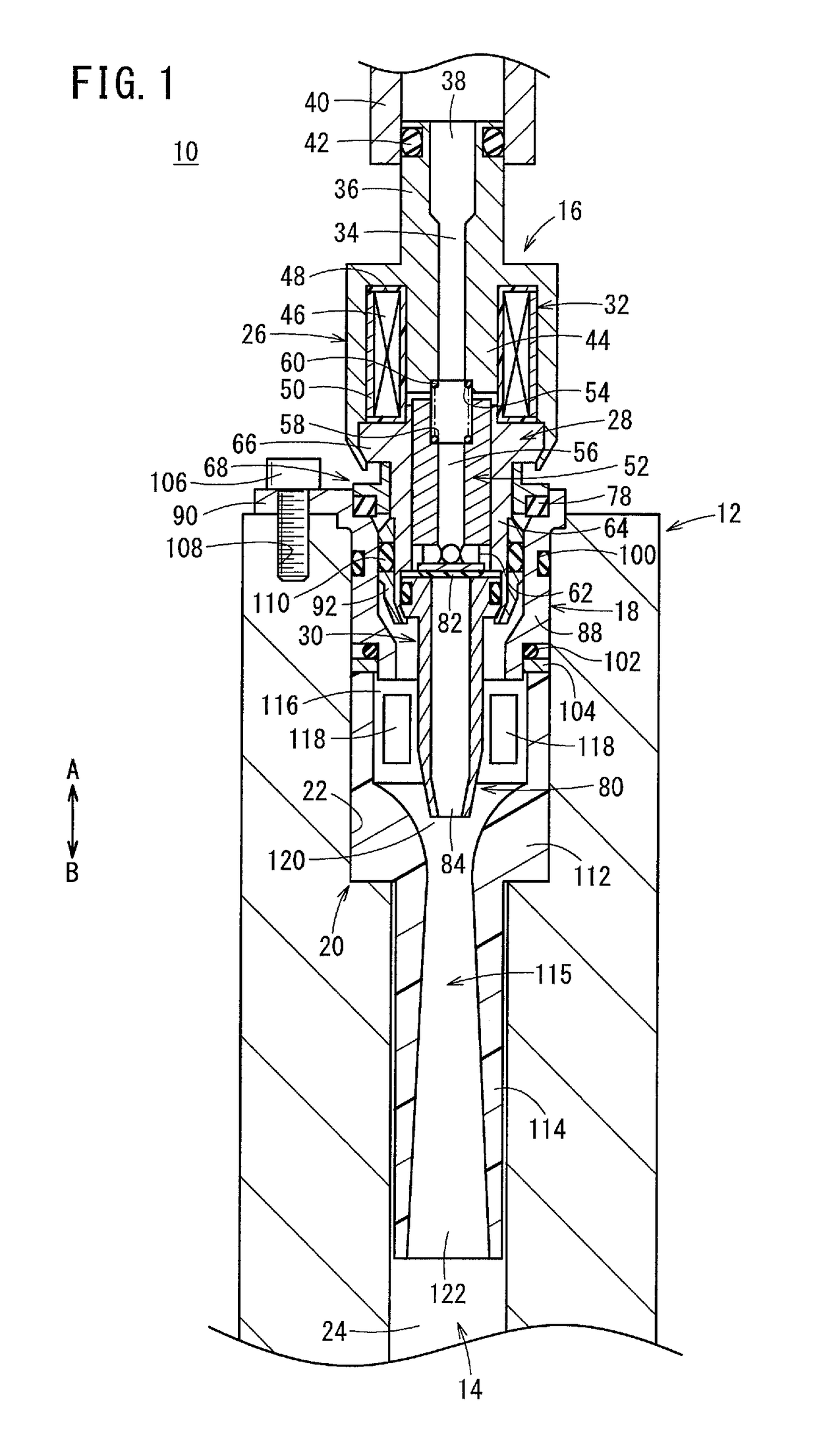
[0020]As shown in FIG. 1, a hydrogen injection apparatus 10 includes an injector 16 provided at an attachment hole 14 of a body 12 for injecting hydrogen, an attachment 18 for fixing the injector 16 to the body 12, and a diffuser 20 for mixing the injected hydrogen with hydrogen discharged from a fuel cell stack (not shown). The attachment hole 14 functions as a fluid channel to flow the hydrogen.

[0021]Hereinafter, a side of the hydrogen injection apparatus 10 where the injector 16 is provided, indicated by an arrow A, will be referred to as the “proximal end side”, and a side of the hydrogen injection apparatus 10 where the diffuser 20 is provided, indicated by an arrow B, will be referred to as the “distal end side”.

[0022]The attachment hole 14 includes a first hole 22 having a large diameter formed on the proximal end side of the body 12 indicated by the arrow A and a second hole 24 having a diameter smaller than that of the first hole 22, and formed on the distal end side of the...


PUM


Abstract

A hydrogen injection apparatus has an injector attached to an attachment hole of a body. The injector can inject hydrogen. A mounting member made of metal is provided on the outer circumferential side of the injector. An annular elastic member is provided in contact with a base of the mounting member. At the time of mounting the injector to the attachment hole, an elastic member and the mounting member are assembled in a manner that the elastic member and the mounting member are accommodated in a support base of an attachment provided at an opening of the attachment hole.

Description

CROSS-REFERENCE TO RELATED APPLICATION[0001]This application is based upon and claims the benefit of priority from Japanese Patent Application No. 2016-032638 filed on Feb. 24, 2016, the contents of which are incorporated herein by reference.BACKGROUND OF THE INVENTION[0002]Field of the Invention[0003]The present invention relates to a hydrogen injection apparatus used in a fuel cell system, for injecting hydrogen.[0004]Description of the Related Art[0005]Conventionally, in fuel cell systems, fuel gas supply apparatuses for supplying a hydrogen gas to fuel cells have been used. For example, as disclosed in Japanese Laid-Open Patent Publication No. 2010-267553, the fuel gas supply apparatus has an injector for injecting hydrogen, and the injector is attached to a support base of a body having a fluid channel to flow the hydrogen gas. The hydrogen injected from a front end (distal end) of the injector flows through the fluid channel, and the hydrogen is supplied from a discharge port ...

Claims


Application Information

Patent Timeline
IPC IPC(8): H01M8/04082
CPCH01M8/04201F04F5/16F04F5/46H01M8/04089Y02E60/50F02M21/02H01M8/04097
Inventor KOYAMA, TOMOYOSHIFUKUDA, TETSUYAINOUE, SATOSHI
Owner HONDA MOTOR CO LTD
Why Eureka
Try Eureka