Thin-type ink-jet printing head and manufacturing method and device thereof

An inkjet print head and technology for manufacturing methods, applied to chemical instruments and methods, digital output to printing units, printing, etc., can solve the problems of inability to apply glue normally, thinning of inkjet print heads, difficulty in ink chambers and Drive device alignment and other issues

Pending Publication Date: 2020-10-23
SUZHOU INST OF NANO TECH & NANO BIONICS CHINESE ACEDEMY OF SCI
View PDF9 Cites 0 Cited by
  • Summary
  • Abstract
  • Description
  • Claims
  • Application Information

AI Technical Summary

Problems solved by technology

However, when the thickness of the mold layer is lower than a certain level, during the process of clamping the mold layer, the mold layer is too thin to withstand the force of clamping, so that bending occurs, resulting in the failure of normal coating. glue
Even if the above-mentioned bottom-thick mold layer is placed flat on the machine and the substrate is attached, because the substrate itself is an opaque material, it is difficult to align the ink chamber and the drive device.
Also, re-clamping a lay-flat ply can damage the ply itself
Therefore, the thinning of current inkjet printheads has great limitations

Method used


Image

  • Thin-type ink-jet printing head and manufacturing method and device thereof
  • Thin-type ink-jet printing head and manufacturing method and device thereof
  • Thin-type ink-jet printing head and manufacturing method and device thereof

Examples


Embodiment 1

[0045] This embodiment provides a method for manufacturing a thin inkjet print head. Such as image 3 As shown, the preparation method includes:

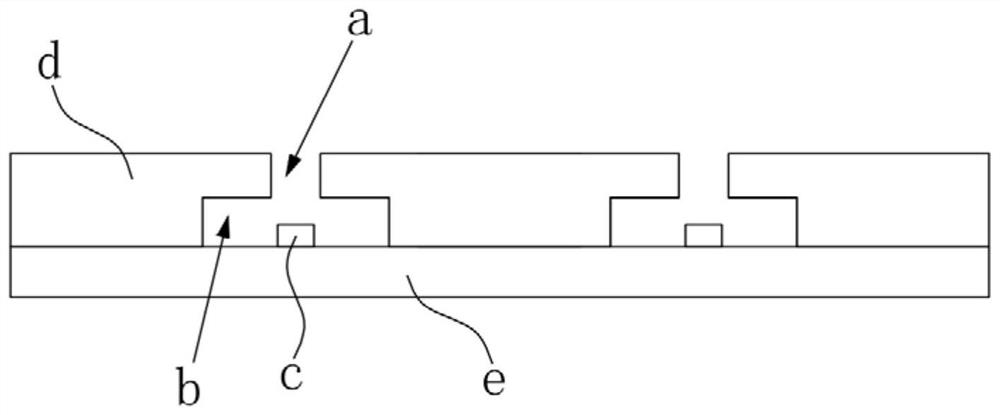
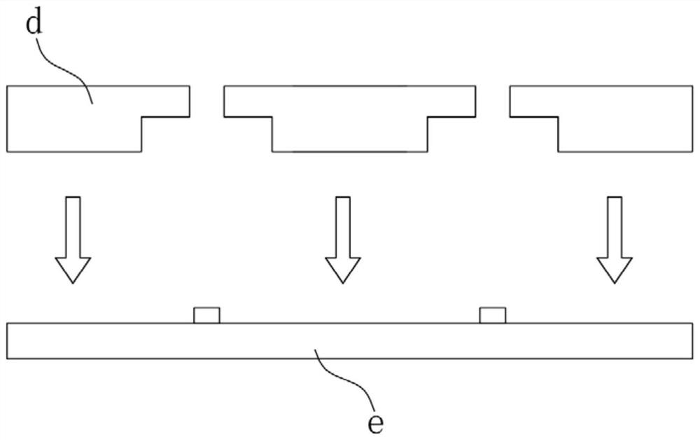
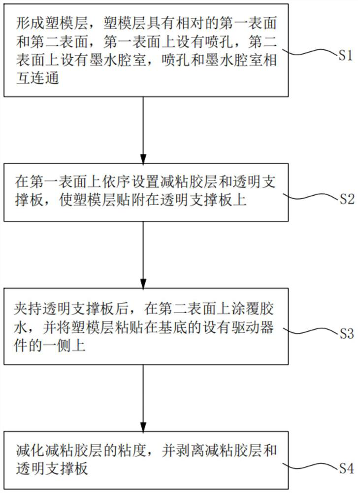
[0046] Step S1, forming a mold layer 3, the mold layer 3 has a first surface 3a and a second surface 3b opposite to each other. The first surface 3a is provided with a nozzle hole 31, and the second surface 3b is provided with an ink chamber 32, and the nozzle hole 31 and the ink chamber 32 communicate with each other.

[0047] Specifically, such as Figure 4a Shown, the step of forming molding layer 3 comprises:

[0048] A pattern corresponding to the ink chamber 32 is formed on the silicon wafer A by photolithography;

[0049] According to the pattern, the silicon wafer A is etched using an ICP (Inductively Coupled Plasma: Inductively Coupled Plasma Etching) process or a RIE (Reactive Ion Etching: Reactive Ion Etching) process to form a The original mold 1 of the groove corresponding to the ink chamber 32;

[0050] pouring c...

Embodiment 2

[0064] This embodiment provides a device for making a thin inkjet print head. The equipment includes: processing module, injection module, reinforcement module, assembly module and stripping module.

[0065] Wherein, the processing module is configured to control the injection molding module, the strengthening module, the assembling module and the stripping module.

[0066] The injection molding module is configured to make a mold layer, the mold layer has a first surface and a second surface opposite to each other, the first surface is provided with nozzle holes, and the second surface is provided with an ink cavity chamber, the nozzle hole and the ink chamber communicate with each other.

[0067] The reinforcement module is configured to sequentially arrange an adhesive-reducing layer and a transparent support plate on the first surface, so that the mold layer is attached to the transparent support plate.

[0068] The assembling module is configured to apply glue on the se...


PUM

PropertyMeasurementUnit
thicknessaaaaaaaaaa

Abstract

The invention discloses a manufacturing method of a thin-type ink-jet printing head. The manufacturing method comprises the steps that a plastic mold layer is formed, the plastic mold layer is provided with a first surface and a second surface which are opposite to each other, a spray hole is formed in the first surface, an ink chamber is formed in the second surface, and the spray hole communicates with the ink chamber; an adhesive reducing layer and a transparent support plate are sequentially arranged on the first surface, and thus the plastic mold layer is adhered to the transparent support plate; after the transparent support plate is clamped, glue is applied on the second surface, and the plastic mold layer is pasted on the side, provided with a driving device, of a substrate; and the viscosity of the adhesive reducing layer is reduced, and the adhesive reducing layer is stripped off the transparent support plate. The invention discloses a device for achieving the manufacturing method. According to the manufacturing method, the technical problems existing in the thinning process of the ink-jet printing heat are solved.

Description

technical field [0001] The invention relates to the technical field of inkjet printers, in particular to a manufacturing method capable of releasing the thickness limitation of a thin inkjet printing head. Background technique [0002] The inkjet print head is one of the core components in the inkjet printer, such as figure 1 As shown, it includes a nozzle hole a and an ink chamber b communicating with the nozzle hole, and a driving device c is also arranged in the ink chamber. The role of the driving device c is to provide energy to the ink in the ink chamber b, so that the ink can be ejected at a certain speed through the nozzle a. [0003] The method usually used in the process of making inkjet printheads at present is the bonding method. Such as figure 2 As shown, the bonding method is to use the injection molding process to form the mold layer d having the structure of the nozzle hole a and the ink chamber b, and then attach the mold layer d to the substrate e on wh...

Claims


Application Information

Patent Timeline
Patent Type & Authority Applications(China)
IPC IPC(8): B41J2/14B41J2/16G06F3/12B29C33/38B29C45/00B29C45/26B32B37/12
CPCB29C33/3842B29C45/00B29C45/26B32B37/1284B41J2/14B41J2/16B41J2/1632B41J2/164G06F3/1278
Inventor 刘志斌谢永林李令英黄哲观张婷婷周岩
Owner SUZHOU INST OF NANO TECH & NANO BIONICS CHINESE ACEDEMY OF SCI
Why Eureka
Try Eureka