Method of manufacturing a bi-metal screw

Inactive Publication Date: 2009-01-15
TOP WELL TECH CORP
View PDF6 Cites 9 Cited by
  • Summary
  • Abstract
  • Description
  • Claims
  • Application Information

AI Technical Summary

Benefits of technology

[0009]The objects of the present invention are to provide a method of manufacturing a bi-metal screw which facilitates to decrease the interspaces accumulated inside the junction of the two materials while welding, and to increase the quality of the screw formation.
[0010]The method of forming a bi-metal screw in accordance with the present invention comprises in sequence a procedure of preparation, a procedure of welding, a procedure of cutting, and a procedure of formation; wherein, a shank p

Problems solved by technology

1. The Interspaces Generated With

Method used


Image

  • Method of manufacturing a bi-metal screw
  • Method of manufacturing a bi-metal screw
  • Method of manufacturing a bi-metal screw

Examples


Example

[0018]Before the present invention is described in greater detail, it should be noted that the like elements are denoted by the same reference numerals throughout the disclosure.

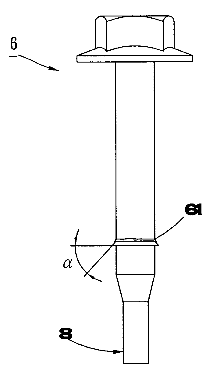
[0019]Referring to FIG. 6, the first preferred embodiment of a method of manufacturing a bi-metal screw 5 comprises a procedure of preparation 51, a procedure of welding 52, a procedure of cutting 53, and a procedure of formation 54. Further referring to FIG. 7, a shank portion 7 and a drilling portion 8 are respectively formed and made of different materials in the procedure of preparation 5; wherein, the shank portion 7 is made of a kind of metal, for instance of a stainless steel, which comprises a screw head 71 formed on one side thereof and a planar welding surface 72 disposed on the other side thereof; furthermore, the drilling portion 8 is made of another kind of metal, for instance of a low-carbon steel, which is susceptible of carburizing-and-quenching, so as to promote the volume of the carbon up t...


PUM

PropertyMeasurementUnit
Angleaaaaaaaaaa

Abstract

The present invention pertains to a method of manufacturing a bi-metal screw comprising a sequence of procedures; wherein, the process preparation is for arranging a shank portion and a drilling portion made of different materials; the shank portion has a planar welding surface defined thereon; in particular, the drilling portion includes a conical section with a conical surface defined on the top face thereof. While operating, the conical section is gradually welded to the planar welding surface to form a composite screw, so as to smooth the air away for preventing the interspaces generated within the junction of the two portions and rendering the composite screw not to be slanted aside. Subsequently, an integral bi-metal screw is formed through the processes of precisely cutting and formation, thereby increasing the quality of the screw.

Description

BACKGROUND OF THE INVENTION[0001]1. Field of the Invention[0002]The present invention relates to a method of forming a screw, in particular a method of manufacturing a bi-metal screw which facilitates to lower the interspaces within the junction of two materials while operating, and to increase the quality of the formation.[0003]2. Description of the Related Art[0004]Referring to FIGS. 1 and 2, a conventional method of manufacturing a bi-metal screw 1 comprising a sequence of procedures, which include a procedure of preparation 11, a procedure of welding 12, a procedure of cutting 13, and a procedure of formation 14; wherein, a shank portion 15 and a drilling portion 16 are arranged in the procedure of preparation 11, which are respectively made of different materials; the shank portion 15 has a screw head 151 formed on one end thereof and a welding surface 152 disposed on the other end thereof; the drilling portion 16 has a drill tip 161 defined at the distal end thereof and an eng...

Claims


Application Information

Patent Timeline
IPC IPC(8): B21H3/02B21K1/56
CPCB21H3/02Y10T29/49881B21K1/56
Inventor HSIEH, YI-LIN
Owner TOP WELL TECH CORP
Why Eureka
Try Eureka