Industrial Ethernet Switch

a technology of industrial ethernet switches and switches, applied in the field of communication, can solve the problems of high implementation cost, unmanaged switches without intelligent features, and inability to meet the form factor and power requirements of commercial off-the-shelf equipment, and achieve the effect of increasing functionality

Active Publication Date: 2008-01-03
CISCO TECH INC
View PDF9 Cites 14 Cited by
  • Summary
  • Abstract
  • Description
  • Claims
  • Application Information

AI Technical Summary

Benefits of technology

[0006] Embodiments of the invention may provide numerous technical advantages. Some embodiments may include some, none, or all of the below described advantages. For example, in one embodiment of the invention a rugged Ethernet switch is provided that includes a plurality of advanced software features such as rapid spanning, multiple spanning, cluster management, and IGMP snooping and querying that provides desired functionality to a user of an Ethernet switch, but is believed to not have been implemented in rugged Ethernet switches previously. According to another embodiment, a temperature sensor and alarm software responsive to the temperature sensor are provided in conjunction with an Ethernet switch to monitor a temperature of the Ethernet switch, which allows user intervention in the case of overheating that might result from placing increased functionality on an Ethernet switch.

Problems solved by technology

Unmanaged switches that do not support intelligent features cannot provide the data transport reliability required by large scale applications specifically for control protocols based on producer-consumer models.
Commercial off-the-shelf equipment do not generally meet the form factor and power requirements of the industry at large and its implementation is costly.

Method used


Image

  • Industrial Ethernet Switch
  • Industrial Ethernet Switch
  • Industrial Ethernet Switch

Examples


Embodiment Construction

[0024] Embodiments of the invention are best understood by referring to FIGS. 1 through 9 of the drawings, like numerals being used for like and corresponding parts of the various drawings.

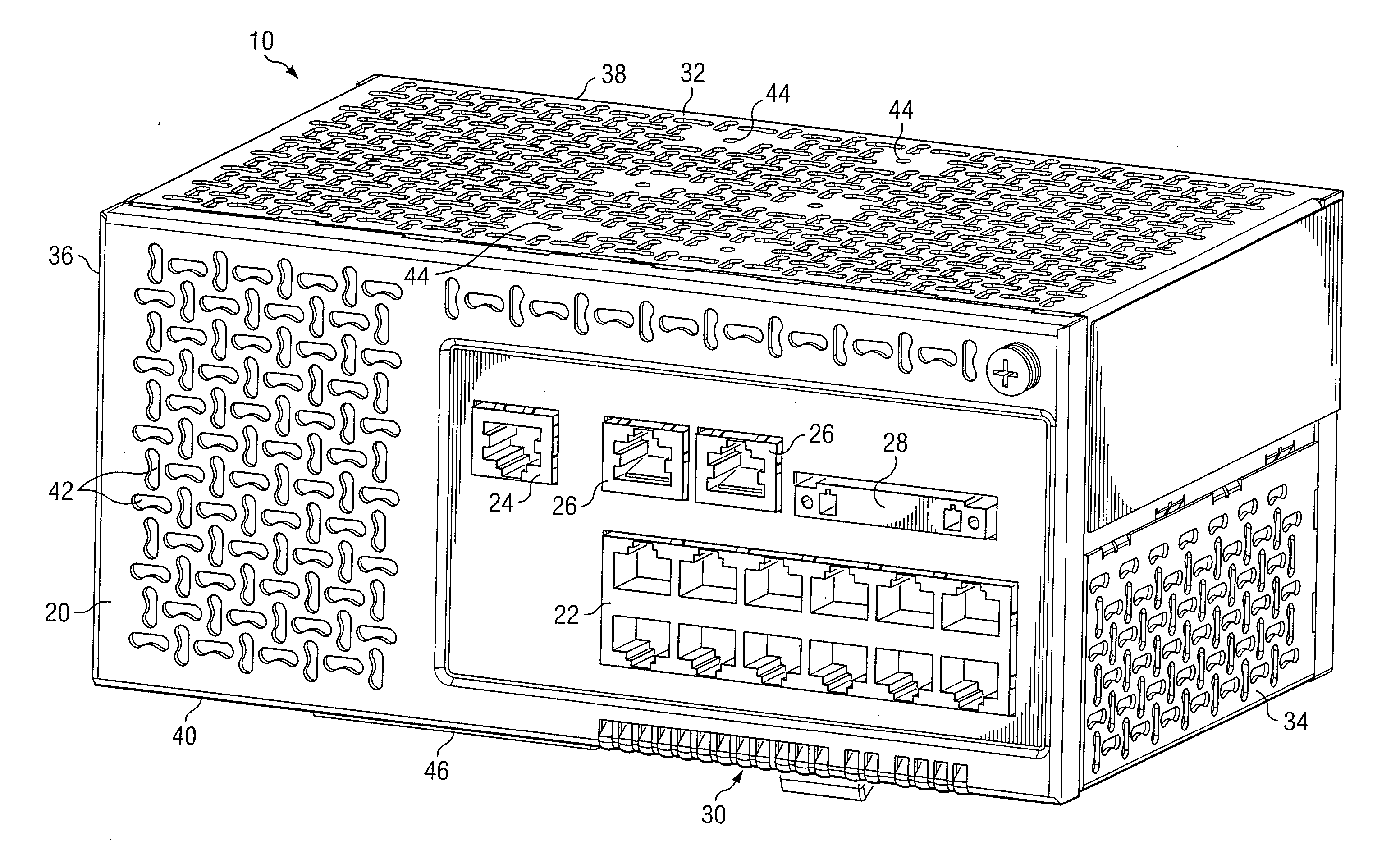
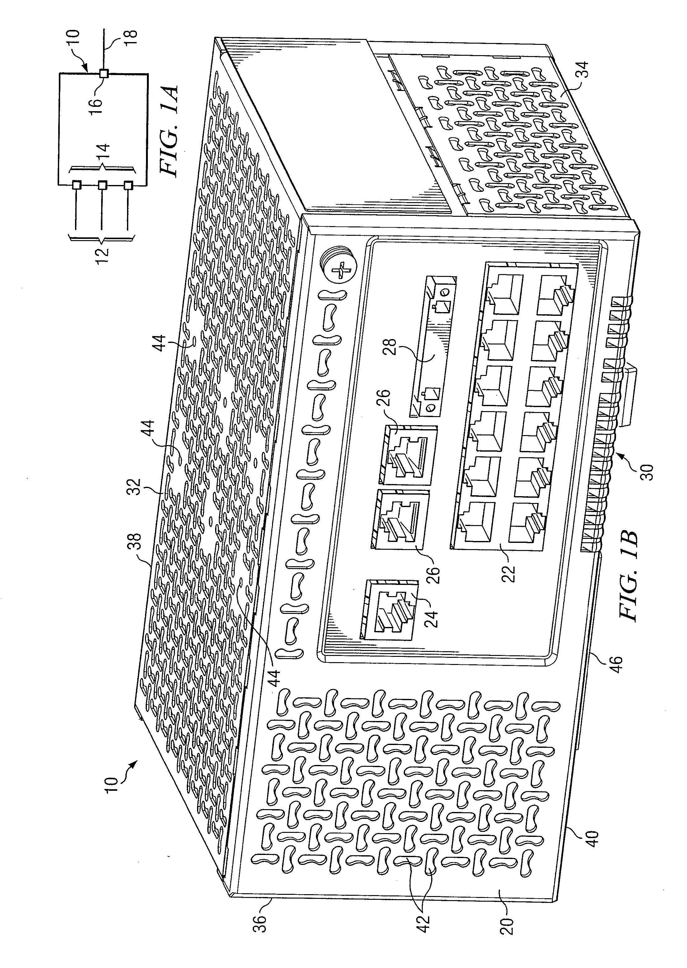
[0025]FIG. 1A is a block diagram illustrating an Ethernet switch 10 according to the teachings of the invention. Ethernet switch 10 receives a plurality of lines 12 at respective ports 14. Ethernet switch 10 may selectively couple, or switch, each line 12 to another line 12 or to an uplink 18 through output ports 16. Ethernet switches may be used in a variety of contexts to communicate voice and data to a desired location and may be located in a variety of locations, such as within a central office of a telecommunications carrier or within a manufacturing or industrial environment.

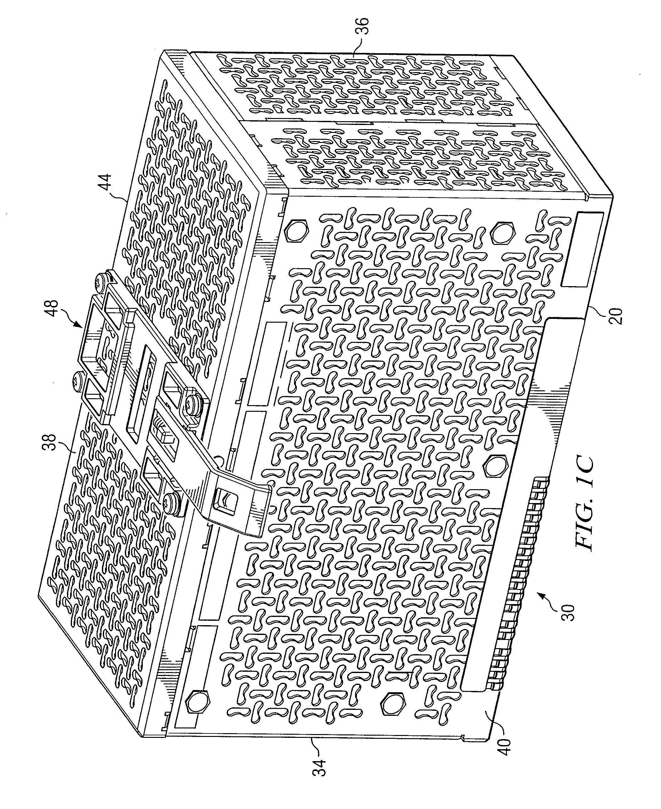
[0026]FIG. 1B illustrates an isometric drawing of Ethernet switch 10 according to the teachings of the invention. In this view the front 20 of Ethernet switch is illustrated. Shown on front 20 of Ethernet switch 10 are...


PUM


Abstract

According to one embodiment of the invention a rugged Ethernet switch includes a housing and a passive cooling system associated with the housing and being devoid of fans as operable to cool the Ethernet switch. Ethernet switch also includes software operable to perform at least one of the functions selected from the group consisting of multiple spanning, rapid spanning, cluster management and IGMP snooping and querying. According to another embodiment, a rugged Ethernet switch includes a housing having a plurality of perforations formed therein for cooling the Ethernet switch. The switch also includes a passive cooling system be devoid of fans and that is operable to cool the Ethernet switch. A temperature sensor is operable to measure a temperature of the Ethernet switch is included as is an alarm software responsive to the temperature sensor and operable to initiate an alarm when a measured temperature of the Ethernet switch exceeds a particular limit.

Description

CROSS-REFERENCE TO RELATED APPLICATION [0001] This application is a continuation of U.S. application Ser. No. 10 / 377,570 filed Feb. 28, 2003 and entitled “Industrial-Ethernet Switch”.TECHNICAL FIELD OF THE INVENTION [0002] This invention relates generally to communications and more particularly to an industrial Ethernet switch with enhanced functionality. BACKGROUND OF THE INVENTION [0003] Ethernet is a standard for communicating both data and voice signals. The use of Ethernet communications in industrial applications is increasing, and in response, Ethernet switches particularly designed for industrial applications are being produced. Previous implementations of Ethernet in industrial applications, such as manufacturing control applications, have relied on simple unmanaged switched that have been “hardened” to withstand the environmental conditions existing on the manufacturing floor or on intelligent managed switches inside temperature controlled enclosures. Unmanaged switches th...

Claims


Application Information

Patent Timeline
Patent Type & Authority Applications(United States)
IPC IPC(8): G08B19/00G06F1/20H05K7/14
CPCG06F1/206H05K7/1464H04L49/40H04L49/351
Inventor NGUYEN, YEN TERESABRENES, MANRIQUE J.COLLINGE, JAMES E.
Owner CISCO TECH INC
Why Eureka
Try Eureka