Deicing system and method

a technology of deicing system and water tank, which is applied in the direction of water heaters, water heaters, immersion heating arrangements, etc., can solve the problems of large temperature gradient between the top and bottom of the water contained within the tank, animal burns, and the typical operation of sinking deicers requires more energy

Inactive Publication Date: 2008-01-03
MILLER MFG
View PDF3 Cites 10 Cited by
  • Summary
  • Abstract
  • Description
  • Claims
  • Application Information

AI Technical Summary

Benefits of technology

[0015]The pump is configured to circulate the water within the water receptacle to prevent temperature gradients within the water.
[0020]Certain embodiments of the present invention provide a system for preventing ice from forming on a surface of water. The system includes an open-ended water receptacle and a deicer.

Problems solved by technology

Additionally, an animal may be burned if it contacts a hot heating element.
Due to the fact that the sinking deicer lies at the bottom of the water receptacle, however, the sinking deicer is configured to heat the entire body of water, instead of just the top layer that is susceptible to freezing.
Consequently, a typical sinking deicer requires more energy to operate than a typical floating deicer.
Additionally, as a tank of water cools, the water contained within the tank may form a significant temperature gradient between the top and the bottom of the tank.
Thus, typical sinking deicers waste energy due to the fact that they usually heat water long after the threat of freezing has been overcome.
Much like a sinking deicer, however, a typical drain plug deicer excessively heats the water within the receptacle, thereby wasting energy.
As discussed above, sinking and drain plug deicers are less efficient than floating deicers.

Method used


Image

  • Deicing system and method
  • Deicing system and method
  • Deicing system and method

Examples


Embodiment Construction

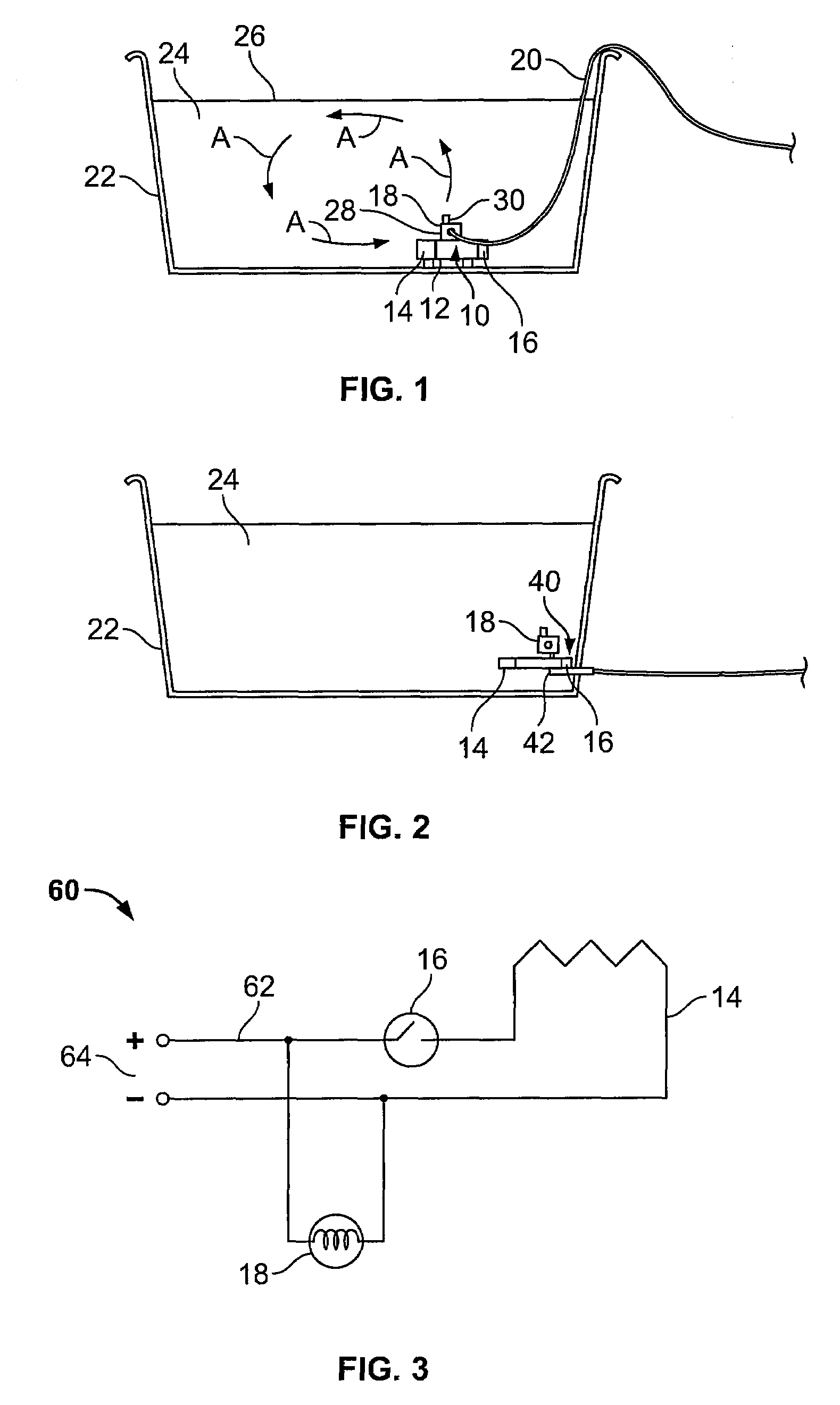
[0030]FIG. 1 illustrates a simplified view of a sinking deicing system 10 according to an embodiment of the present invention. The sinking deicing system 10 includes a main body 12 that supports a heating element 14 and a temperature sensor 16. The heating element 14 may be a coil heater, while the temperature sensor 16 may be a thermostat, thermometer, or the like. A fluid pump 18 is secured on, to, and / or within the main body 12. For example, the fluid pump 18 may be disposed on top of the main body 12 above the heating element 14 and the temperature sensor 16. The heating element 14, the temperature sensor 16, and the fluid pump 18 are electrically connected to an insulated power cord 20 that connects the deicing system 10 to a source of power, such as a standard wall outlet. Optionally, the deicing system 10 may be powered by batteries.

[0031]Each of the heating element 14, the temperature sensor 16, and the fluid pump 18 may also be electrically connected to a processing unit (n...


PUM


Abstract

A deicing system configured to heat water within a water receptacle includes a main body supporting a temperature sensor, a heating element, and a pump. The main body is positioned proximate a base of the water receptacle. The temperature sensor is configured to detect the temperature of the water. The heating element is configured to heat the water when a temperature of the water approaches a freezing point. The pump is configured to circulate the water within the water receptacle to prevent temperature gradients within the water.

Description

RELATED APPLICATIONS[0001]The present application relates to and claims priority from U.S. Provisional Application No. 60 / 811,527, entitled “Deicer With Convection Pump,” filed Jun. 7, 2006, which is also hereby incorporated by reference in its entirety.FIELD OF THE INVENTION[0002]Embodiments of the present invention generally relate to a deicing system and method, and more particularly to a deicing system and method that circulates fluid within a fluid receptacle in order to uniformly disperse heated water and reduce or eliminate temperature gradients within the fluid.BACKGROUND OF THE INVENTION[0003]Conventional electric water deicers are used to keep areas of livestock water tanks and ponds free from ice during winter months. One type of deicer is a floating deicer in which a buoyant member such as a buoyant ring is attached to a heating element so that the deicer may float on the surface of the water. Another type of deicer is a sinking deicer that is configured to lay at the bo...

Claims


Application Information

Patent Timeline
Patent Type & Authority Applications(United States)
IPC IPC(8): H05B3/80
CPCE02B15/02H05B2214/02H05B3/80
Inventor REUSCHE, THOMAS K.CHUMBLEY, PHILIP E.
Owner MILLER MFG
Why Eureka
Try Eureka