Cavity ventilation

a ventilation system and cavity technology, applied in the direction of sustainable transportation, mechanical equipment, machines/engines, etc., can solve the problems of increased temperature within the cavity, damaged or degraded, heat sensitive devices mounted within the cavity, etc., and achieve the effect of avoiding temperature gradients

Inactive Publication Date: 2015-08-04
ROLLS ROYCE PLC
View PDF14 Cites 8 Cited by
  • Summary
  • Abstract
  • Description
  • Claims
  • Application Information

AI Technical Summary

Benefits of technology

[0014]A plurality of ventilation ducts may be angularly spaced about said outer wall. Each duct may have an associated flow diverter which promotes the vortical flow component. Each flow diverter promotes a vortical flow in the same orientation about the inner wall. Each flow diverter may be arranged to produce a corresponding jet emanating there-from in use, the jets being oriented to complement or promote the vortical flow in the cavity. In an alternative explanation, each flow diverter may be considered to promote a corresponding vortex and the vortices of each of the flow diverters overlap to create a global vortex about the inner wall within the cavity. This creates a more uniform temperature distribution throughout air in the cavity and serves to avoid the temperature gradients caused by jetting of coolant against hot surfaces. A more even flow profile downstream is thus created.

Problems solved by technology

A gas turbine engine and, in particular, the combustors produce a significant amount of heat during use, which results in greatly elevated temperatures within the cavity.
The accessories mounted within the cavity are heat sensitive to a greater or lesser extent and can be damaged or degraded at such prevailing operating temperatures.
Whilst steps have been taken to produce accessories which can withstand such elevated temperatures without imminent failure, it is well-known that the increased temperatures can impact on the operational life of such components.
The ventilation flow through the cavity represents a parasitic loss to the efficiency of the gas turbine engine, causing reduced engine thrust and increased fuel consumption.

Method used


Image

  • Cavity ventilation
  • Cavity ventilation
  • Cavity ventilation

Examples


Embodiment Construction

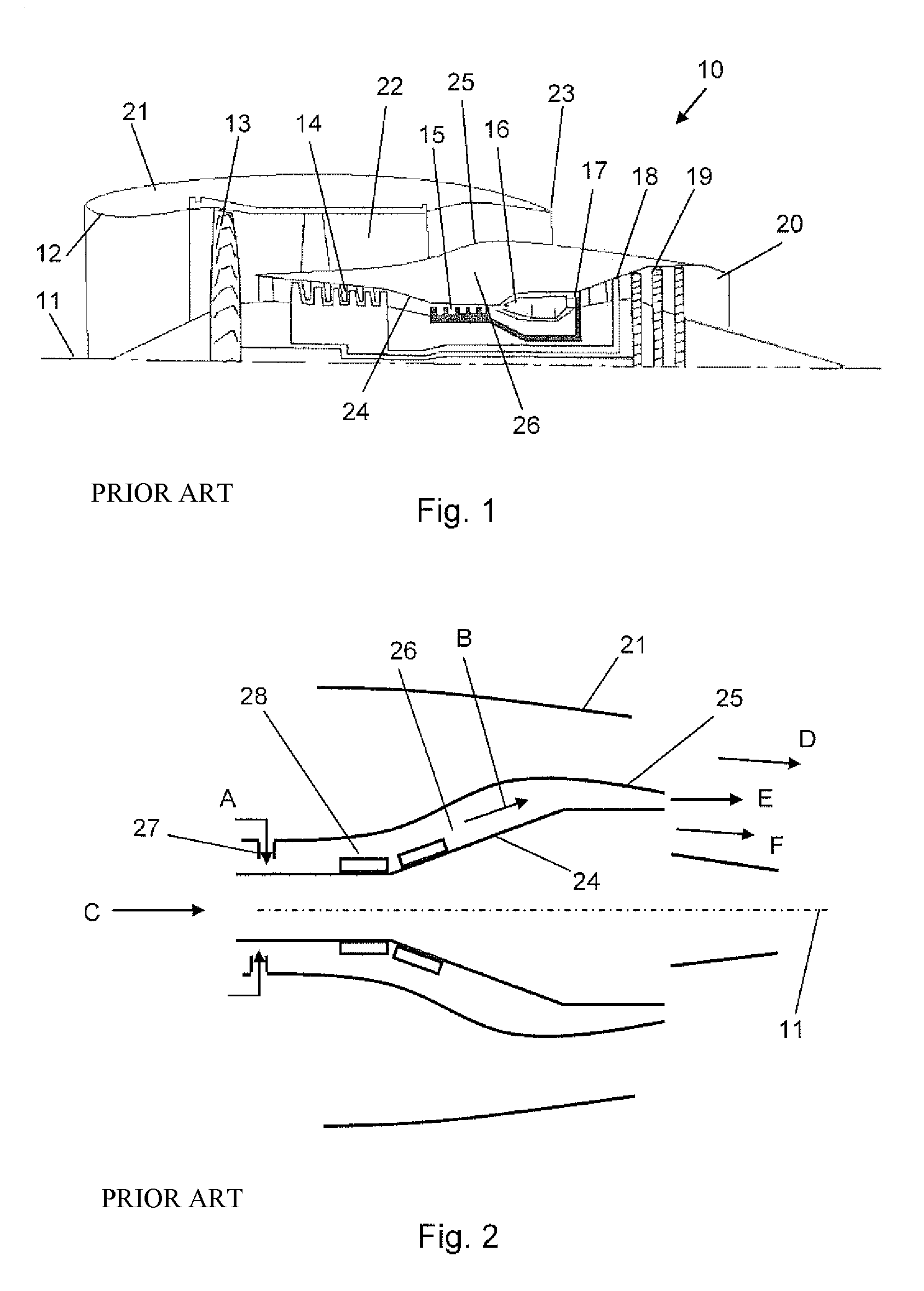
[0029]With reference to FIG. 1, a ducted fan gas turbine engine generally indicated at 10 has a principal and rotational axis 11. The engine 10 comprises, in axial flow series, an air intake 12, a propulsive fan 13, an intermediate pressure compressor 14, a high-pressure compressor 15, combustion equipment 16, a high-pressure turbine 17, and intermediate pressure turbine 18, a low-pressure turbine 19 and a core engine exhaust nozzle 20. A nacelle 21 generally surrounds the engine 10 and defines the intake 12, a bypass duct 22 and a bypass exhaust nozzle 23.

[0030]The gas turbine engine 10 works in a conventional manner so that air entering the intake 11 is accelerated by the fan 13 to produce two air flows: a first air flow into the intermediate pressure compressor 14 and a second air flow which passes through a bypass duct 22 to provide propulsive thrust. The intermediate pressure compressor 14 compresses the air flow directed into it before delivering that air to the high pressure ...


PUM


Abstract

A ventilation arrangement for an annular cavity located about the core engine of a gas turbine, the annular cavity having an axis and an inner wall located about the axis and an outer wall radially spaced from the inner wall, the outer wall being interposed between the cavity and an engine bypass duct. The ventilation arrangement comprises a plurality of ventilation ducts passing through said outer wall and providing for fluid communication between the bypass duct and the cavity and a flow diverter arranged at an oblique angle to a radial alignment with said axis so as to induce in the ventilation flow from said ducts a vortical flow within the cavity about the inner wall such that said vortical flow has a vortex width of magnitude substantially equal to that of a diameter of the annular cavity. The ducts may be shaped to provide the flow diverter. The internal geometry of the ducts may provide for a sudden expansion to control the exit profile of the flow into the cavity.

Description

FIELD OF THE INVENTION[0001]The present invention relates to a cavity ventilation system and more particularly, although not exclusively, to a ventilation system for cooling a cavity located about a heat source, such as, for example, a gas turbine engine.BACKGROUND OF THE INVENTION[0002]Ducted fan jet engines for aircraft applications have a core engine located within an engine casing or cowl. The engine fan blades and casing are further surrounded by a nacelle spaced from the casing to provide a bypass duct about the core engine through which compressed air is forced by the fan blades.[0003]A cavity is defined between the engine casing and the nacelle. The difference in profile between the core engine and the nacelle results in a cavity of considerable volume, in which it is known to mount accessories such as sensors and electrical or electronic components so as to make efficient use of the available space.[0004]The cavity in question may be referred to as the engine compartment or...

Claims


Application Information

Patent Timeline
Patent Type & Authority Patents(United States)
IPC IPC(8): F02K3/02F02K3/06F02C7/18F01D25/14
CPCF01D25/14F02K3/06F02C7/18Y02T50/675F05D2260/2212F05D2260/608Y02T50/60
Inventor HUSSAIN, ZAHID M.
Owner ROLLS ROYCE PLC
Why Eureka
Try Eureka