Magnetic resonance imaging device

a magnetic resonance imaging and magnetic field technology, applied in the direction of measuring devices, magnetic measurements, instruments, etc., can solve the problems of difficult to improve the performance vibration generation, and the likelihood of deformation and generation so as to reduce the vibration of gradient magnetic field coils and cables

Active Publication Date: 2007-12-11
HITACHI MEDICAL CORP +1
View PDF9 Cites 8 Cited by
  • Summary
  • Abstract
  • Description
  • Claims
  • Application Information

AI Technical Summary

Benefits of technology

[0006]An object of the present invention is to provide an MRI apparatus having a configuration that reduces vibration of a gradient magnetic field coil and cables.
[0007]To achieve the aforementioned object, in the MRI apparatus according to the first embodiment of the present invention, a static magnetic field generating source comprises a magnetic field generating-coil and a closed vessel enclosing the magnetic field generating coil inside, and the closed vessel has a rigid structure in order to prevent transmission of vibration generated by a gradient magnetic field generating part to other members via the closed vessel. The gradient magnetic field generating part is supported on a face of the closed vessel on the imaging space side. Because the closed vessel has a rigid structure, it becomes unlikely to vibrate, thereby vibration generated in the closed vessel by vibration of the gradient magnetic field generating part can be suppressed, and vibration of the gradient magnetic field generating part fixed on such a closed vessel can be suppressed. Furthermore, because vibration of the closed vessel itself is suppressed, transmission of vibration from the gradient magnetic field generating part to other members via the closed vessel can be prevented.
[0008]The aforementioned rigid structure can comprise at least one connector which connects a face on the imaging space side and an opposite face of the closed vessel inside the closed vessel. By connecting the confronting faces of the closed vessel as described above, the rigidity of the closed vessel can be improved.

Problems solved by technology

Therefore, there is a problem that this vibration is transmitted from the body of the gradient magnetic field generating coil via cables thereof to the static magnetic field generating source, and thus the static magnetic field generating source vibrates.
However, in the configuration described in Japanese Patent Unexamined Publication (KOKAI) No. 2002-52004 mentioned above, the gradient magnetic field coil is supported by the supporting system at the central part thereof, and therefore the gradient magnetic field coil is likely to deform and also generate vibration.
For this reason, it becomes difficult to improve the performances of the gradient magnetic field coil (for example, linearity of the gradient magnetic field, low vibration property of the gradient magnetic field coil etc.).
Moreover, vibration is generated also in cables connected in order to supply a current to the gradient magnetic field coil, and reduction of this vibration is not taken into consideration.
Furthermore, how to draw cables for supplying a current to the gradient magnetic field coil and piping for circulating cooling water to the outside is not taken into consideration, either.

Method used


Image

  • Magnetic resonance imaging device
  • Magnetic resonance imaging device
  • Magnetic resonance imaging device

Examples


first embodiment

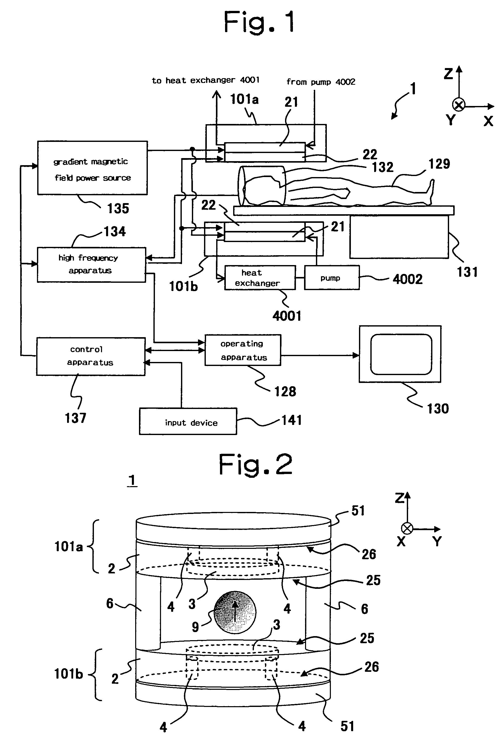
[0059]The MRI apparatus according to the first embodiment comprises, as a whole view thereof is shown in FIGS. 1 and 33, a static magnetic field generating apparatus 1, a gradient magnetic field coil 21, a high frequency irradiating coil 22, a bed 131 on which a subject 129 is laid, and a high frequency receiving coil 132. Besides these, the apparatus includes a gradient magnetic field power source 135, a high frequency apparatus 134, a control apparatus 137, an operating apparatus 128, an input device 141 and a display 130 as control and operation systems. Moreover, as shown in FIG. 1, the apparatus also comprises a heat exchanger 4001 and a pump 4002, which supply a refrigerant such as cooling water to the gradient magnetic field coil 21.

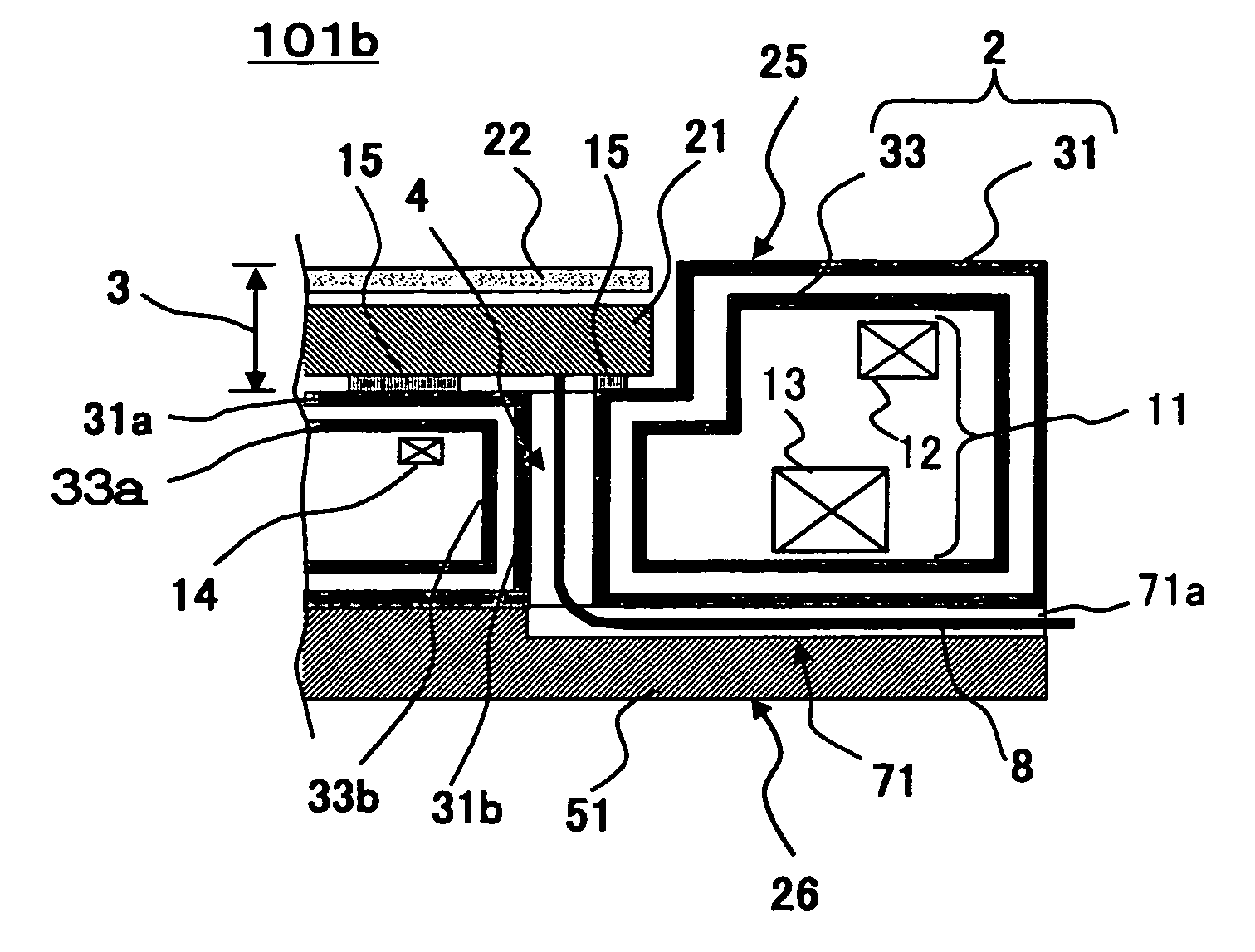
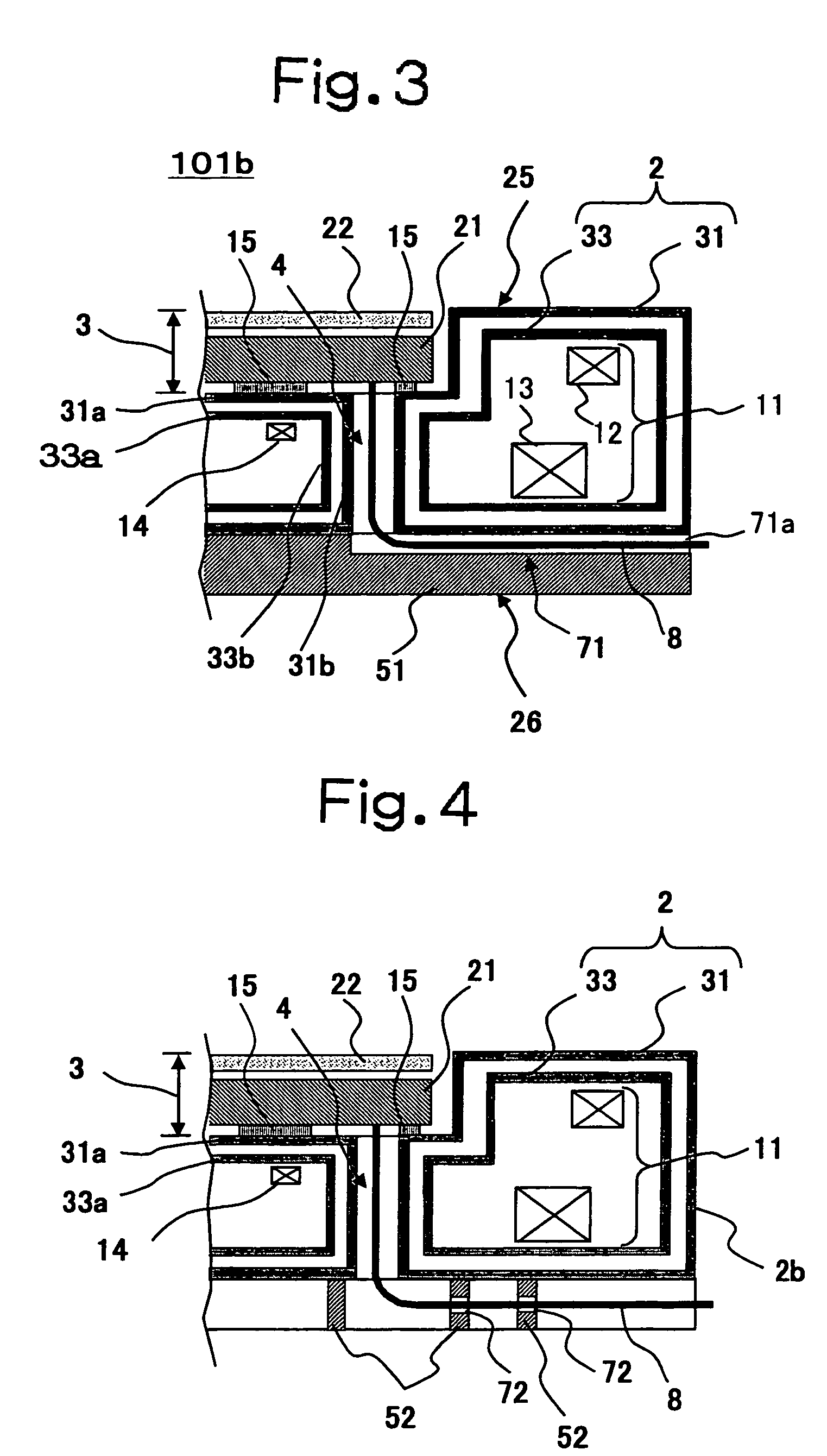
[0060]The static magnetic field generating apparatus 1 comprises, as shown in FIGS. 2, 3 and 33, a pair of superconducting magnets 101a and 10b, which are opposingly disposed on the upper side and lower side, and two of connecting columns 6 connec...

second embodiment

[0080]The MRI apparatus according to the second embodiment of the present invention will be explained by referring to FIGS. 4, 5(a) and (b). The MRI apparatus according to the second embodiment uses a grid reinforcing member 52 as a reinforcing member fixed to the cryostat 2 instead of the thick plate reinforcing member 51 used in the first embodiment. The other structure is the same as that of the first embodiment. By using the grid reinforcing member 52, it is possible to further reduce the weight compared with the case of using the thick plate reinforcing member 51 while enhancing the rigidity of the cryostat 2. Further, by providing the through-hole 4 at a position corresponding to an opening of the grid, the cables 8 or cooling pipes can be drawn out to the back surface side without providing through-holes in the grid reinforcing member 52. Further, even when the cables 8 etc. are drawn out to the outer peripheral surface side of the grid reinforcing member 52, it is sufficient...

third embodiment

[0081]The MRI apparatus of the third embodiment will be explained by referring to FIG. 6. Although the MRI apparatus of the third embodiment uses a thick plate reinforcing member 51 as a reinforcing member like the first embodiment, a thick plate reinforcing member 51 consisting of a plurality of separate members is used. In the example shown in FIG. 5, the circular thick plate reinforcing member 51 is divided into two of members 51a and 51b in a semicircular shape beforehand, and the members 51a and 51b are disposed so that a gap 73 should be secured between them and the opening of the through-hole 4 of the cryostat 2 should locate between them. The gap 73 can be thereby used as a pathway for disposing the cables 8 or cooling pipes. Therefore, it is not necessary to form a through-hole 71 like the thick plate reinforcing member 51 shown in FIG. 3, resulting in an advantage that manufacture of the thick plate reinforcing member 51 becomes easy.

[0082]In the example shown in FIG. 6, t...


PUM


Abstract

An MRI apparatus having a configuration that reduces vibration of a static magnetic field generating source is provided. A closed vessel 2 of the static magnetic field generating source is provided with a rigid structure 4 for preventing transmission of vibration generated from a gradient magnetic field generating part 21 to other members via the closed vessel 2. The rigid structure 4 uses, for example, a connecting part 4 that connects a face 25 on the imaging space side and a face 26 confronting it. The rigidity of the closed vessel is thereby increased, and therefore vibration transmitted from the gradient magnetic field generating part can be reduced. The connecting part can have a through-hole structure, and in such a case, internal space of through-hole can be used for drawing cables.

Description

TECHNICAL FIELD[0001]The present invention relates to a magnetic resonance imaging apparatus (henceforth referred to as “MRI apparatus”).BACKGROUND ART[0002]MRI apparatuses include those of a type using one pair of opposingly disposed static magnetic field generating sources, in which a uniform static magnetic field region is formed in the space between the pair of static magnetic field generating sources. An imaging portion of a subject is disposed in this uniform static magnetic field region and imaged. An MRI apparatus using opposingly disposed static magnetic field generating sources has advantages that it can give open feeling to a subject, and the subject is more easily accessed by an operator compared with an MRI apparatus of a type using a cylindrical static magnetic field generating source. As the static magnetic field generating source, a permanent magnet, resistive type magnet or superconducting magnet is generally used.[0003]A gradient magnetic field generating coil and ...

Claims


Application Information

Patent Timeline
Patent Type & Authority Patents(United States)
IPC IPC(8): G01V3/00G01R33/385
CPCG01R33/3854G01R33/3856
Inventor KUROME, AKIRASAKAKIBARA, KENJITAKESHIMA, HIROTAKAYATSUO, TAKESHIWATANABE, HIROYUKIWADAYAMA, YOSHIHIDEMOTOSHIROMIZU, HIROFUMISUZUKI, KUNIHITO
Owner HITACHI MEDICAL CORP
Why Eureka
Try Eureka