Temperature-compensated optical fiber component

a technology of optical fiber and component, applied in the direction of optics, optical waveguide light guide, instruments, etc., can solve the problems of changing the predetermined tension applied to the optical fiber, the temperature compensating mechanism cannot effectively work, etc., to achieve the desired optical quality, reduce heat transfer, and improve the accuracy of the bragg grating

Inactive Publication Date: 2006-01-31
FURUKAWA ELECTRIC CO LTD
View PDF6 Cites 6 Cited by
  • Summary
  • Abstract
  • Description
  • Claims
  • Application Information

AI Technical Summary

Benefits of technology

[0009]It is an object of the present invention to provide a temperature-compensated optical fiber component so as to preserve its desired optical quality even if an external force is applied thereto, or its environmental temperature may rapidly change, or there is a heat source in its vicinity, or even after it is used over a long period of time.
[0010]According to the present invention, an optical fiber component comprises an optical fiber, an inner package connected to the optical fiber, the inner package having a portion for processing a light transmitted through the optical fiber, and outputting the processed light, cover means for covering the inner package and permitting the optical fiber to be guided out of the optical fiber component, the cover means including an outer package surrounding an outside of the inner package in a circumferential direction, and heat insulating means for reducing heat transfer between the outer package and the inner package.
[0011]According to this component, the outer package prevents the inner package from being deformed by an external force, such a deformation deteriorating the accuracy of the Bragg grating. The heat insulating means protects rapid heat transfer to the inner package from outside owing to a change of an environmental temperature, and prevents the inner package from having a temperature gradient even though there is a heat source in its vicinity. More specifically, when the processing portion is a Bragg grating formed on the optical fiber, the outer package prevents a change in the tension of the Bragg grating caused by the deformation of the inner package. The heat insulating means can include an air layer or a heat insulating member provided between the inner package and the outer package, which enhancing heat insulation from the outside to preserve the thermal uniformity of the inner package.

Problems solved by technology

However, the aforementioned temperature-compensating mechanism cannot effectively work if an external force is applied to the optical fiber component to deform a fiber-supporting portion, or the optical fiber component is used under circumstances where it is partially heated, or the predetermined tension applied to the optical fiber is changed with the lapse of time.

Method used


Image

  • Temperature-compensated optical fiber component
  • Temperature-compensated optical fiber component
  • Temperature-compensated optical fiber component

Examples


Embodiment Construction

[0021]Embodiments of the invention will now be described with reference to the accompanying figures, wherein like numerals refer to like elements throughout. The terminology used in the description presented herein is not intended to be interpreted in any limited or restrictive manner, simply because it is being utilized in conjunction with a detailed description of certain specific embodiments of the invention. Furthermore, embodiments of the invention may include several novel features, no single one of which is solely responsible for its desirable attributes or which is essential to practicing the invention herein described.

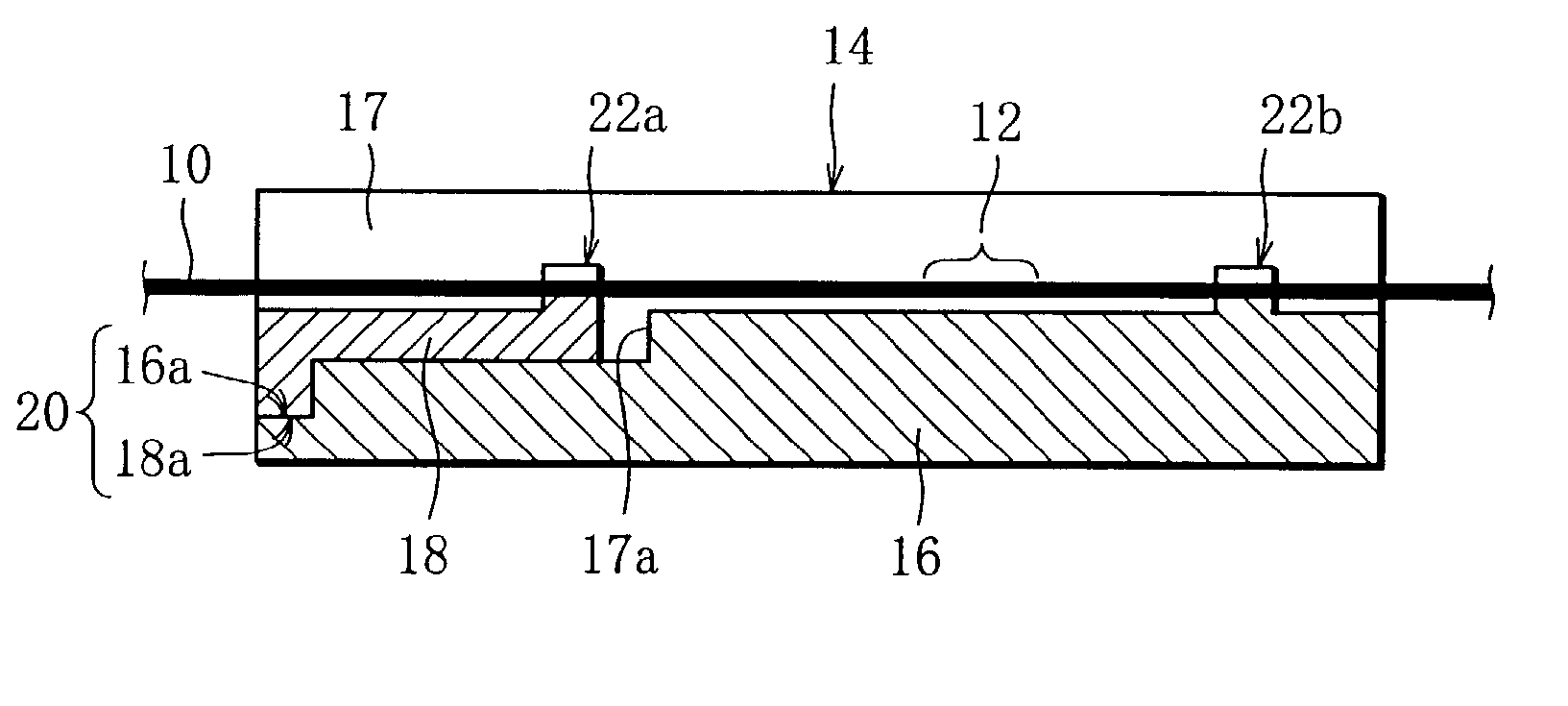
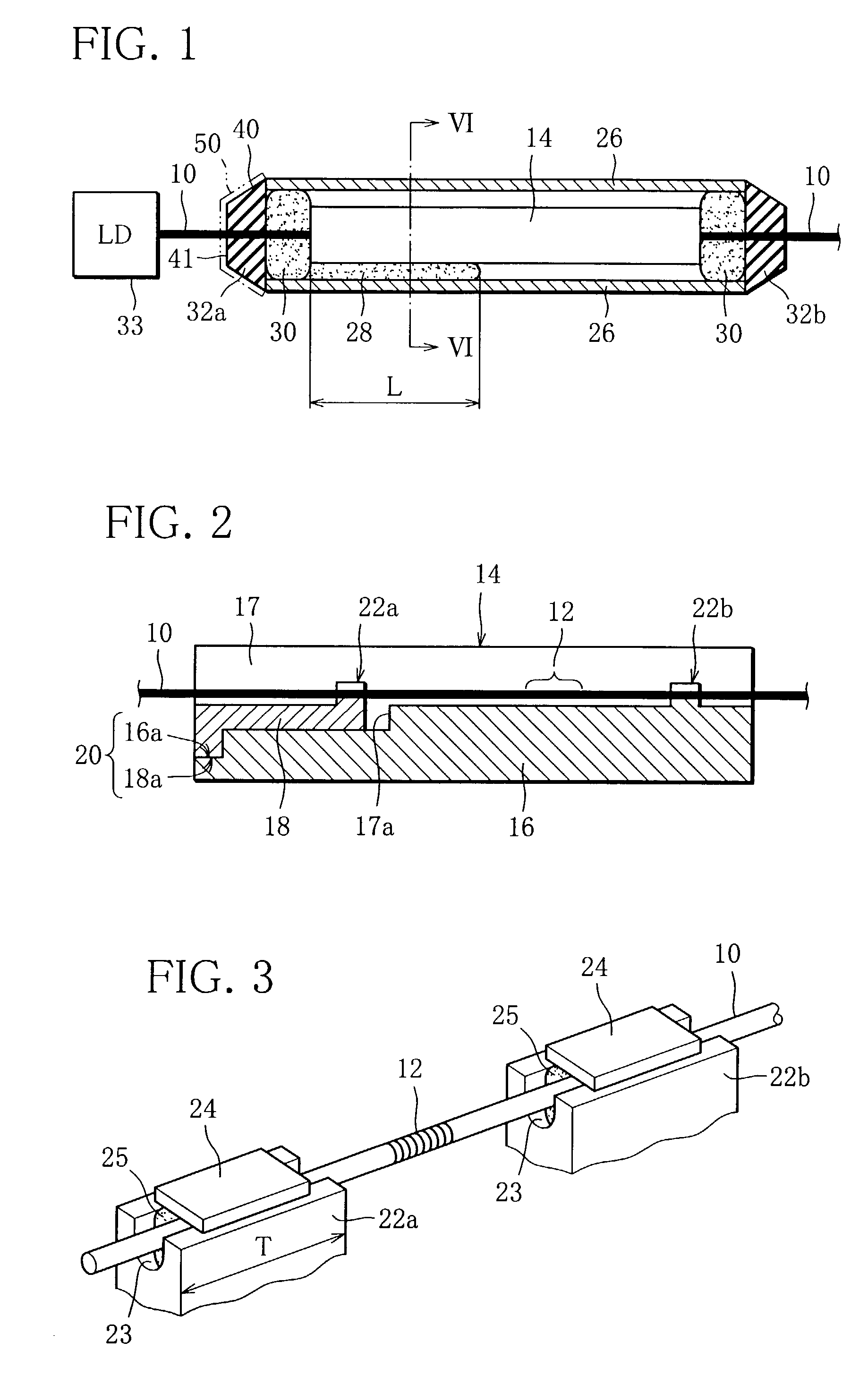
[0022]FIG. 1 shows a temperature-compensated optical fiber component according to an embodiment of the invention. The optical fiber component includes a temperature-compensating package 14, and an optical fiber 10 extending through the package 14. As shown in FIG. 2, a Bragg grating 12 is formed on the optical fiber 10, where the effective refractive index n i...


PUM


Abstract

A temperature-compensated optical fiber component for use in high-density WDM optical communication includes an optical fiber which has a Bragg grating serving as a monochromatic filter, an inner package which supports the optical fiber and causes the Bragg grating to have a temperature-compensating capability, and an outer package arranged outside the inner package. A clearance having a heat insulating function is provided between the outer package and the inner package.

Description

BACKGROUND OF THE INVENTION[0001]1. Field of the Invention[0002]This invention relates to an optical fiber component used in the field of optical communications, and more particularly to a temperature-compensated optical fiber component, suitably used in a WDM (Wavelength Division Multiplexing) communication system.[0003]2. Description of the Related Art[0004]Conventionally, a temperature-compensated optical fiber component is known which has an optical fiber grating as part of an optical fiber.[0005]At the optical fiber grating, the effective refractive index of a core of the optical fiber is periodically changed along the axis of the optical fiber. The optical fiber grating is used for reflecting a light having a relatively narrow wavelength range which is called a Bragg reflection wavelength as a center wavelength. The Bragg reflection wavelength is determined by a Bragg grating period and the effective refractive index of the fiber core. Here, the Bragg reflection wavelength λ, ...

Claims


Application Information

Patent Timeline
Patent Type & Authority Patents(United States)
IPC IPC(8): G02B6/34G02B6/02
CPCG02B6/0218
Inventor SHINOZAKI, ATSUSHIYODO, SHIGEHITOOTA, TOSHIHIKO
Owner FURUKAWA ELECTRIC CO LTD
Why Eureka
Try Eureka