Conversion of static diagnostic procedure to dynamic test plan method and apparatus

a static diagnostic and test plan technology, applied in the field of static diagnostic procedures, can solve problems such as the inability of relativly inexperienced operators to perform advanced diagnostic procedures and diagnose complex operational or medical problems

Active Publication Date: 2008-01-03
SPX CORP
View PDF20 Cites 14 Cited by
  • Summary
  • Abstract
  • Description
  • Claims
  • Application Information

AI Technical Summary

Benefits of technology

[0008]In accordance with one aspect of the present invention, a computer-implemented method of converting a tree-graph representation of a diagnostic procedure into a dynamic decision sequencing representation based on a plurality of elementary diagnostic tests for use with a diagnostic plan generator can include reading a tree-graph that represents the diagnostic procedure and identifying an end node of the tree graph. The method can further include associating the end node with a failure mode, and tracing a path through one or more intermediate nodes to a root node.
[0009]In accordance with another aspect of the present invention, a computer program product for converting a tree-graph representation of a diagnostic procedure into a dynamic decision sequencing representation based on a plurality of elementary diagnostic tests for use with a diagnostic plan generator, including a computer-readable medium encoded with instructions configured to be executed by a processor in order to perform predetermined operations that include reading a tree-graph that represents the diagnostic procedure and identifying an end node of the tree graph. The predetermined operations can further include associating the end node with a failure mode, tracing a path through one or more intermediate nodes to a root node, and generating an initial failure mode test corresponding to the failure mode based on the path.
[0010]In accordance with yet another aspect of the present inve

Problems solved by technology

With such a system, a relatively inexperienced operator may perform advanced

Method used


Image

  • Conversion of static diagnostic procedure to dynamic test plan method and apparatus
  • Conversion of static diagnostic procedure to dynamic test plan method and apparatus
  • Conversion of static diagnostic procedure to dynamic test plan method and apparatus

Examples


Embodiment Construction

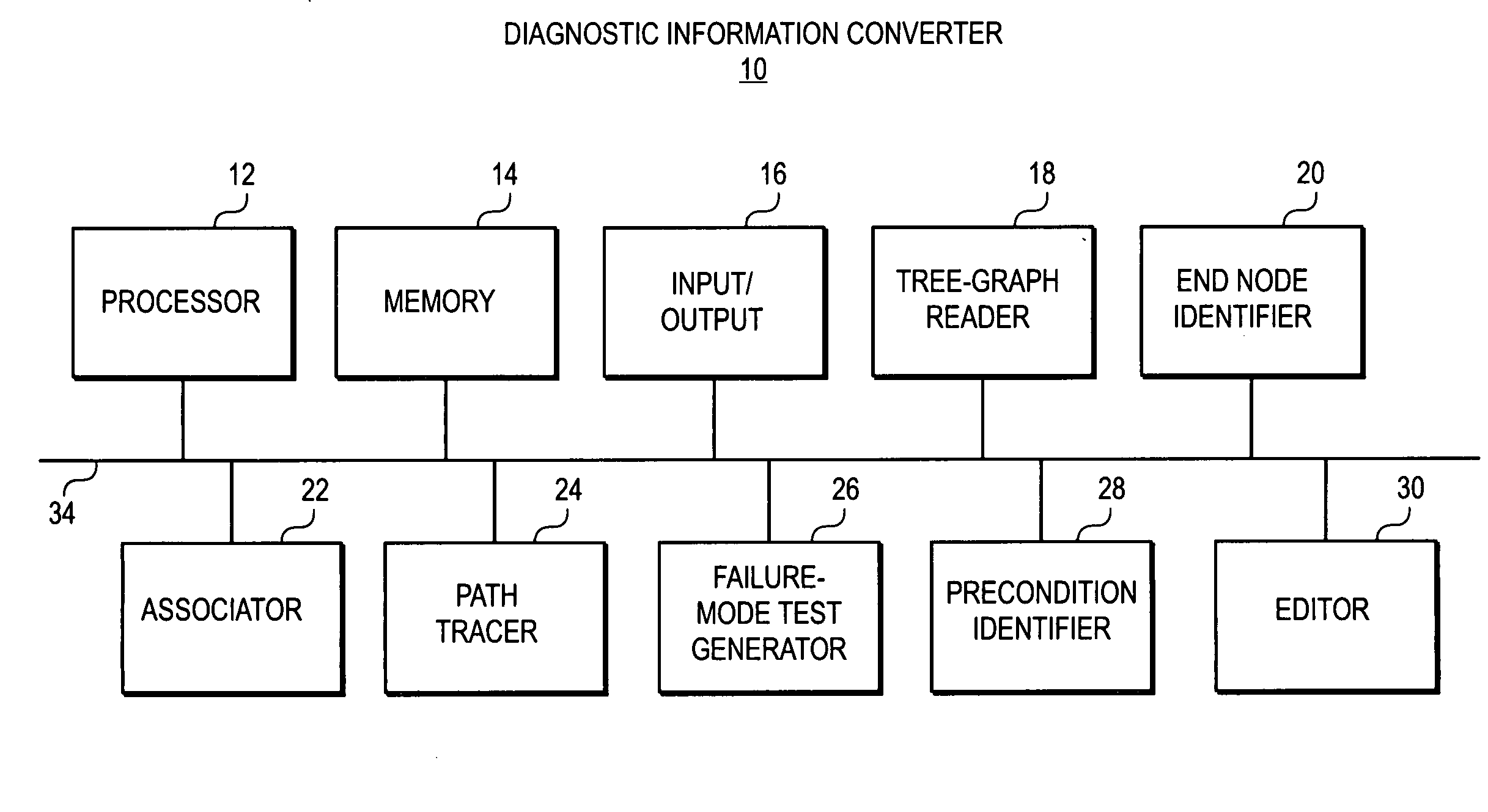
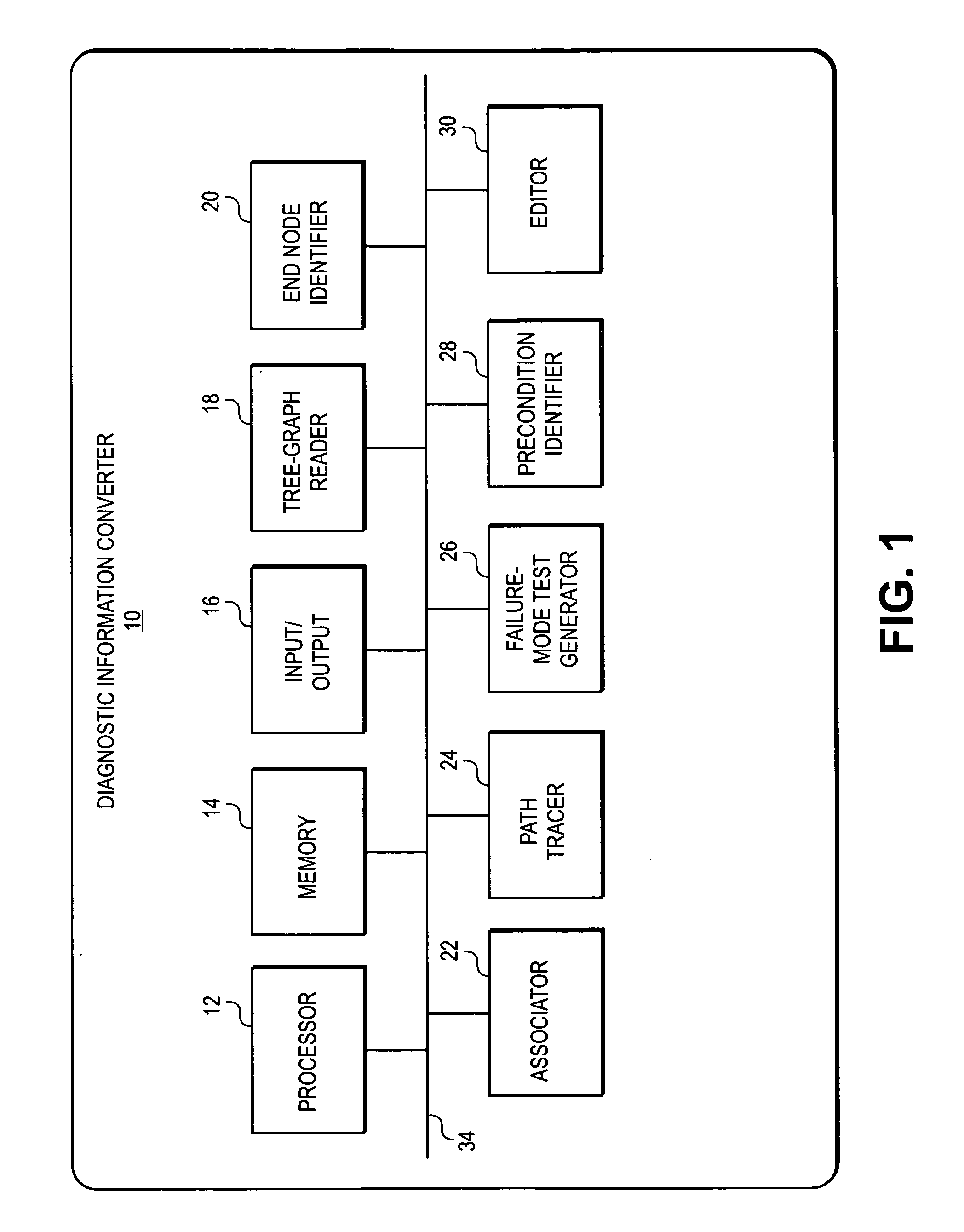
[0018]An embodiment in accordance with the present invention provides a diagnostic information converter that can convert or translate diagnostic information for use with a diagnostic system from one type of organization or format that can be processed by one method into a second type of organization or format that can be processed by a second method. For example, diagnostic procedures for use with a diagnostic system can be based on diagnostic information that is organized or processed in one of a variety of different formats or methods. Thus, in some cases it can be useful to convert or translate a diagnostic procedure that is organized or processed in one format or method into a diagnostic test sequence that is organized or processed in a second format or method.

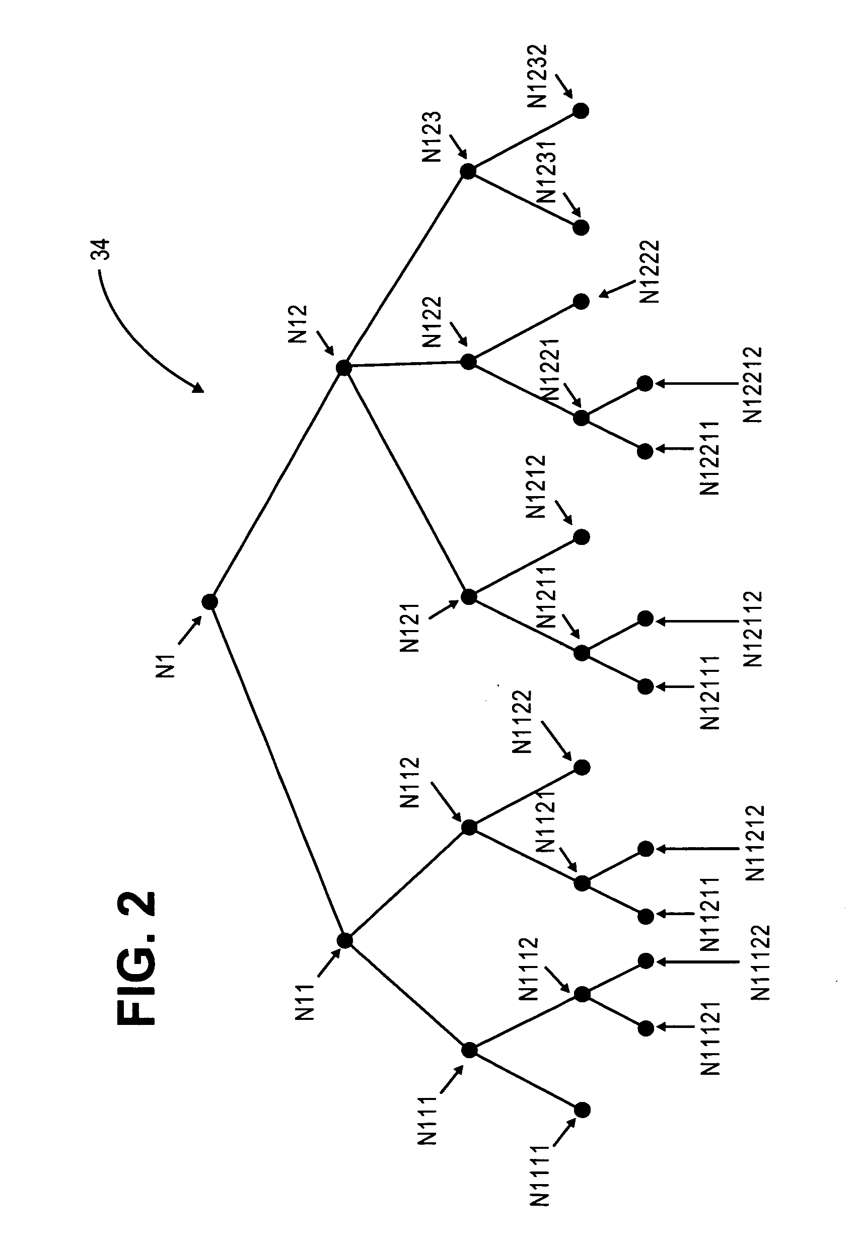
[0019]For example, in some systems a diagnostic procedure can be based on a static diagnostic fault tree. In this scenario, the diagnostic system may use intermediate results at each test step, or node of the fault tree, ...


PUM


Abstract

A diagnostic information converter reads an existing static diagnostic procedure in the form of a tree graph and generates a diagnostic Failure Modes and Effects Analysis that can be used in the generation of a dynamic diagnostic test plan. The converter identifies the end nodes of the graph and associates a specific failure mode with each of the end nodes. In addition, the converter traces a unique path from each end node along successive branches through one or more intermediate nodes to the root node, and from each of the paths derives an initial failure mode test including the test steps corresponding to the root node, the intermediate nodes and the end node. The converter further identifies and annotates precondition nodes that correspond to a vehicle state or condition, rather than to an actual diagnostic test step and allows a user to edit the initial failure mode tests.

Description

FIELD OF THE INVENTION[0001]The present invention relates generally to diagnostic equipment. More particularly, the present invention relates to the conversion or translation of a static diagnostic procedure, such as a tree-graph representation of a vehicle diagnostic test procedure, into a dynamic decision sequencing diagnostic test plan.BACKGROUND OF THE INVENTION[0002]Diagnostic systems are used by technicians and professionals in virtually all industries to perform basic and advanced system testing functions. For example, in the automotive, trucking, heavy equipment and aircraft industries, diagnostic test systems provide for vehicle onboard computer fault or trouble code display, interactive diagnostics, multiscope and multimeter functions, and electronic service manuals. In the medical industry, diagnostic systems provide for monitoring body functions and diagnosis of medical conditions, as well as system diagnostics to detect anomalies in the medical equipment.[0003]In many i...

Claims


Application Information

Patent Timeline
IPC IPC(8): G06F11/00
CPCG06N5/003G06N7/00G06N5/02G06N5/01
Inventor UNDERDAL, OLAV M.GILBERT, HARRY M.PORTYANKO, OLEKSIYMAYES, RANDY L.FOUNTAIN, GREGORY J.WITTLIFF, WILLIAM W.
Owner SPX CORP
Why Eureka
Try Eureka