Support structure for control pedal of vehicle

a technology for supporting structures and control pedals, which is applied in mechanical control devices, instruments, tractors, etc., can solve the problems of difficulty in allowing the control pedal to reliably the support shaft of the control pedal is likely to drop out of the pedal bracket, so as to prevent the impact energy during a vehicle collision and reliably restrict the accidental drop out of the control pedal

Active Publication Date: 2008-01-10
AUTO TECH CORP +1
View PDF9 Cites 18 Cited by
  • Summary
  • Abstract
  • Description
  • Claims
  • Application Information

AI Technical Summary

Benefits of technology

[0009]In view of the above circumstances, it is an object of the present invention to provide a support structure for a vehicle control pedal, capable of preventing impact energy during a vehicle collision from being input to a leg of a driver through the control pedal while reliably restricting accidental drop-out of the control pedal in a normal condition.

Problems solved by technology

However, if a large load is applied to the control pedal downwardly, for example, due to an excessive pedal depressing operation by a driver, the support shaft of the control pedal is likely to drop out of the pedal bracket.
In the support structure disclosed in Patent Publication 3, the control pedal is likely to be inclined due to a load obliquely applied thereto in a course of the expanding deformation of the pedal bracket during a vehicle collision, and thereby cause difficulty in allowing the control pedal to reliably drop out of the pedal bracket.

Method used


Image

  • Support structure for control pedal of vehicle
  • Support structure for control pedal of vehicle
  • Support structure for control pedal of vehicle

Examples


Embodiment Construction

[0018]With reference to the accompanying drawings, a preferred embodiment of the present invention will now be described.

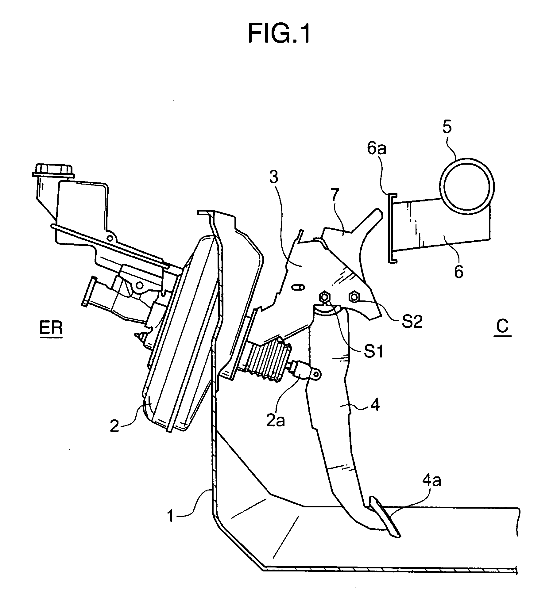
[0019]FIG. 1 is a schematic side view showing a support structure for a vehicle control pedal, according to one embodiment of the present invention. In FIG. 1, the reference numeral 1 indicates a dash panel. The dash panel 1 is disposed to define an engine compartment ER on a front side thereof, and a passenger compartment C on a rear side thereof. The dash panel 1 has one surface which faces the engine compartment ER and fixedly mounts a brake booster 2 thereto, and the other surface which faces the passenger compartment C and fixedly mounts a pedal bracket 3 thereto. The pedal bracket 3 supports a brake pedal 4 swingably in a frontward / rearward direction (i.e., longitudinal direction) of a vehicle body. In a conventional manner, the brake booster 2 is connected to the brake pedal 4 through a push rod 2a. Specifically, when a pedal depressing portion (i.e., pedal...


PUM


Abstract

Disclosed is a support structure for a vehicle control pedal, which comprises a pedal bracket (3) supporting the control pedal (4) through a first support shaft (S1) inserted through a support hole (303), a swingable lever (7) adapted to, during a vehicle collision, come into interference with a vehicle body member (6) so as to be swingingly moved about a second support shaft (S2) while pushing the first support shaft (S1) downwardly to allow the first support shaft (S1) to drop out of the support hole (303), and a drop-out restriction member (8) engaged by a pin member (20) and coupled to the swingable lever (7) in a relatively unswingable manner, so as to restrict the drop-out of the first support shaft (S1). The support structure is designed such that, according to the swing movement of the swingable lever (7) during the vehicle collision, the restriction on drop-out of the first support shaft (S1) by the drop-out restriction member (8) is removed to allow the first support shaft (S1) to drop out of the support hole (303). The support structure of the present invention can prevent impact energy during a vehicle collision from being input to a leg of a driver through the control pedal while reliably restricting accidental drop-out of the control pedal in a normal condition.

Description

BACKGROUND OF THE INVENTION[0001]1. Field of the Invention[0002]The present invention relates to a support structure for a control pedal of a vehicle.[0003]2. Description of the Related Art[0004]Generally, a vehicle control pedal, such as a brake pedal or a clutch pedal, adapted to be swingingly operated by a foot of a driver, is supported relative to a dash panel by a pedal bracket. Specifically, the bracket is fixed to the dash panel, and an upper end of the control pedal is pivotally supported by the petal bracket through a support shaft extending in a width, i.e., lateral, direction of a vehicle body, so that the control pedal is swingably supported relative to the dash panel. In such a vehicle control pedal, it is desired to employ a mechanism for preventing impact energy during a vehicle collision (frontal collision) from being input to a leg of a driver through the control pedal.[0005]As techniques for coping with the demand, JP 2005-510785A (Patent Publication 1) discloses a...

Claims


Application Information

Patent Timeline
Patent Type & Authority Applications(United States)
IPC IPC(8): G05G1/14G05G1/32
CPCB60R21/09B60T7/065Y10T74/20888Y10T74/20528G05G1/32
Inventor TOKUMO, MASAYUKIHIURA, TETSUOISHIDA, HIROFUMI
Owner AUTO TECH CORP
Why Eureka
Try Eureka