
Fluid Energy-Harnessing Apparatus

a technology of fluid energy and apparatus, which is applied in the direction of electric generator control, rotors, machines/engines, etc., can solve the problems of creating barriers to migrating fish and upsetting the natural high and low water flow cycles, and achieves the effect of simple and effective manner

Inactive Publication Date: 2008-01-10
DIEDERICH JURGEN
View PDF5 Cites 28 Cited by
  • Summary
  • Abstract
  • Description
  • Claims
  • Application Information

AI Technical Summary

Benefits of technology

[0005] The present invention is directed to a conveyor-type fluid energy-harnessing apparatus in which reversible fluid foils permit energy to be extracted from the moving fluid, in particular wind, along the upstream reach and the downstream reach in a simple and effective manner.

Problems solved by technology

Building dams creates problems, including flooding of land, creating barriers to migrating fish and upsetting the natural high and low water flow cycles.

Method used


Image

  • Fluid Energy-Harnessing Apparatus
  • Fluid Energy-Harnessing Apparatus
  • Fluid Energy-Harnessing Apparatus

Examples


first wind machine embodiment

[0038] This aspect of the invention is described with reference to FIGS. 11-25 and is directed to a first example of an apparatus 10 that harnesses energy from the wind.

Basic Structure

[0039] This apparatus is comprises a support structure 88, see FIGS. 11 and 12, that supports upper and lower closed loop guide track ways 90, 92.

[0040] The upper and lower horizontal track ways 90, 92 support a series of fluid foils in the form of sails 94, each sail 94 extending from a sail mast 96 with the aid of upper and lower booms 97. Each sail mast 96 is fitted with rollers 98 which are held captive in the upper and lower closed loop track ways 90, 92 that allow the rollers to move in a horizontal fashion along a closed loop path defined by the upper and lower closed loop track ways.

[0041]FIG. 13 is a simplified cross-sectional view of the upper track way 90 illustrated in FIGS. 11 and 12. The distance between the round tubing 102 of the upper track way is sized so that and the roller 98 r...

second wind machine embodiment

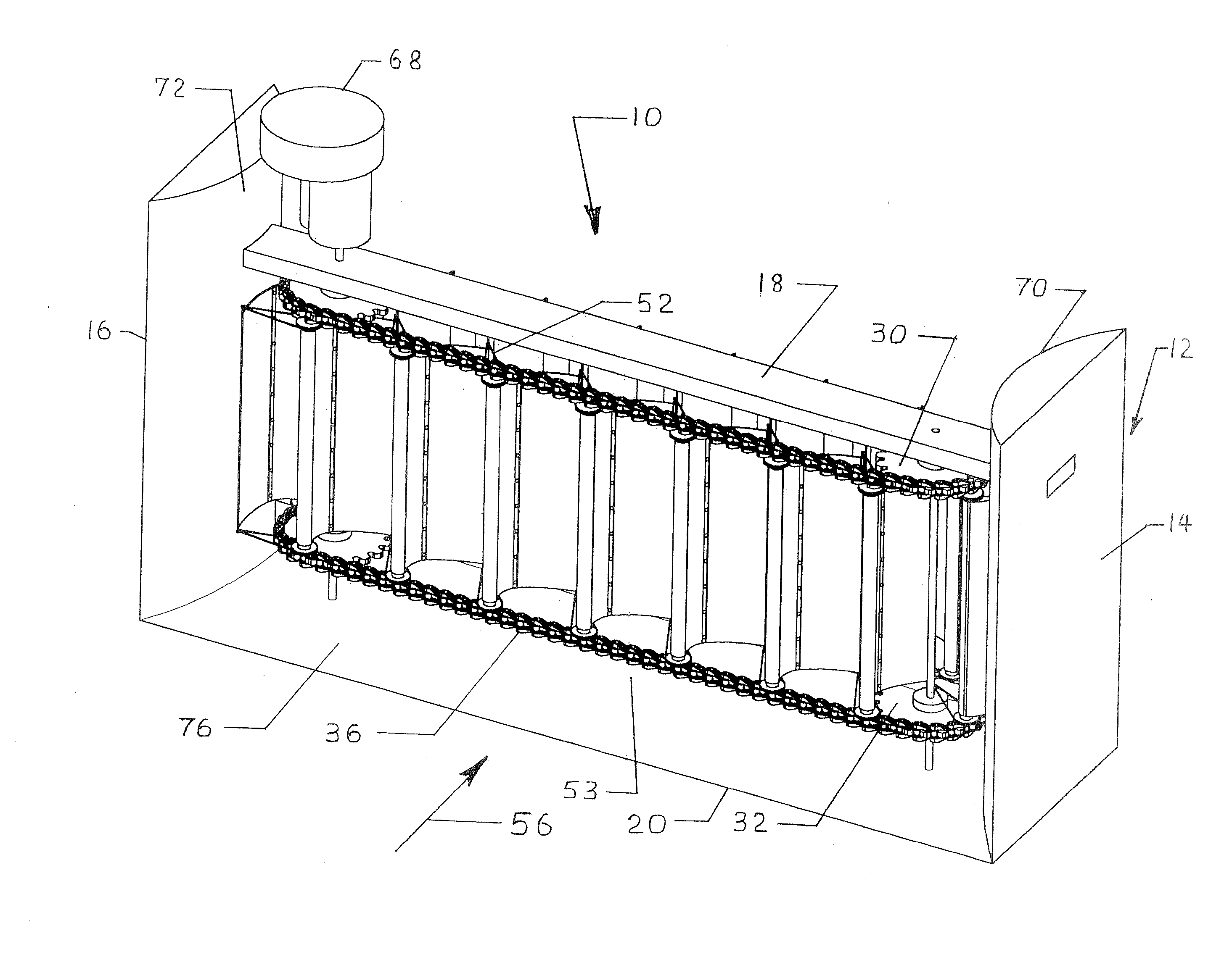
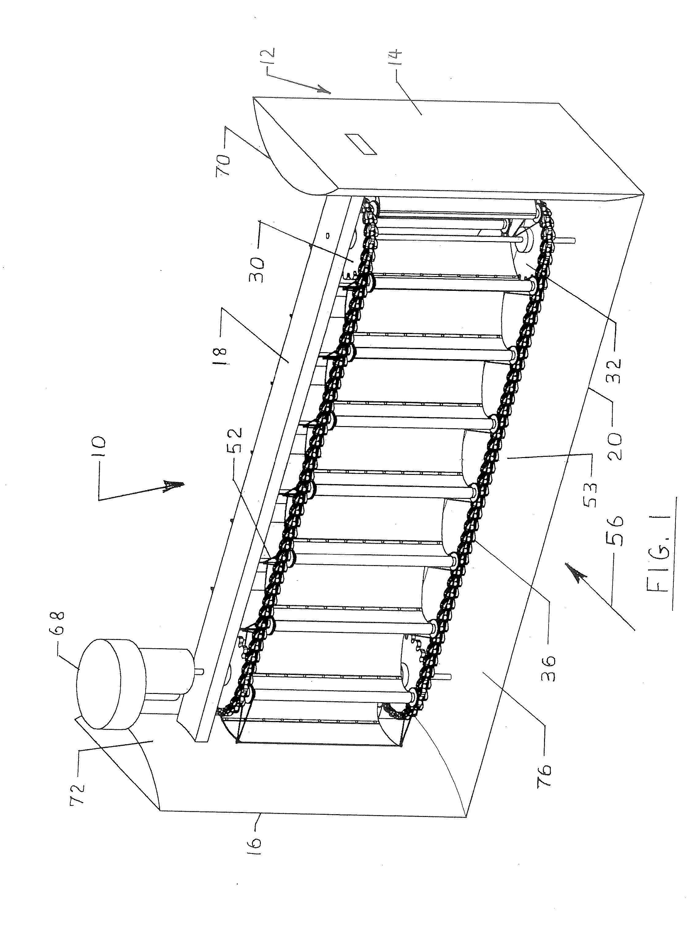
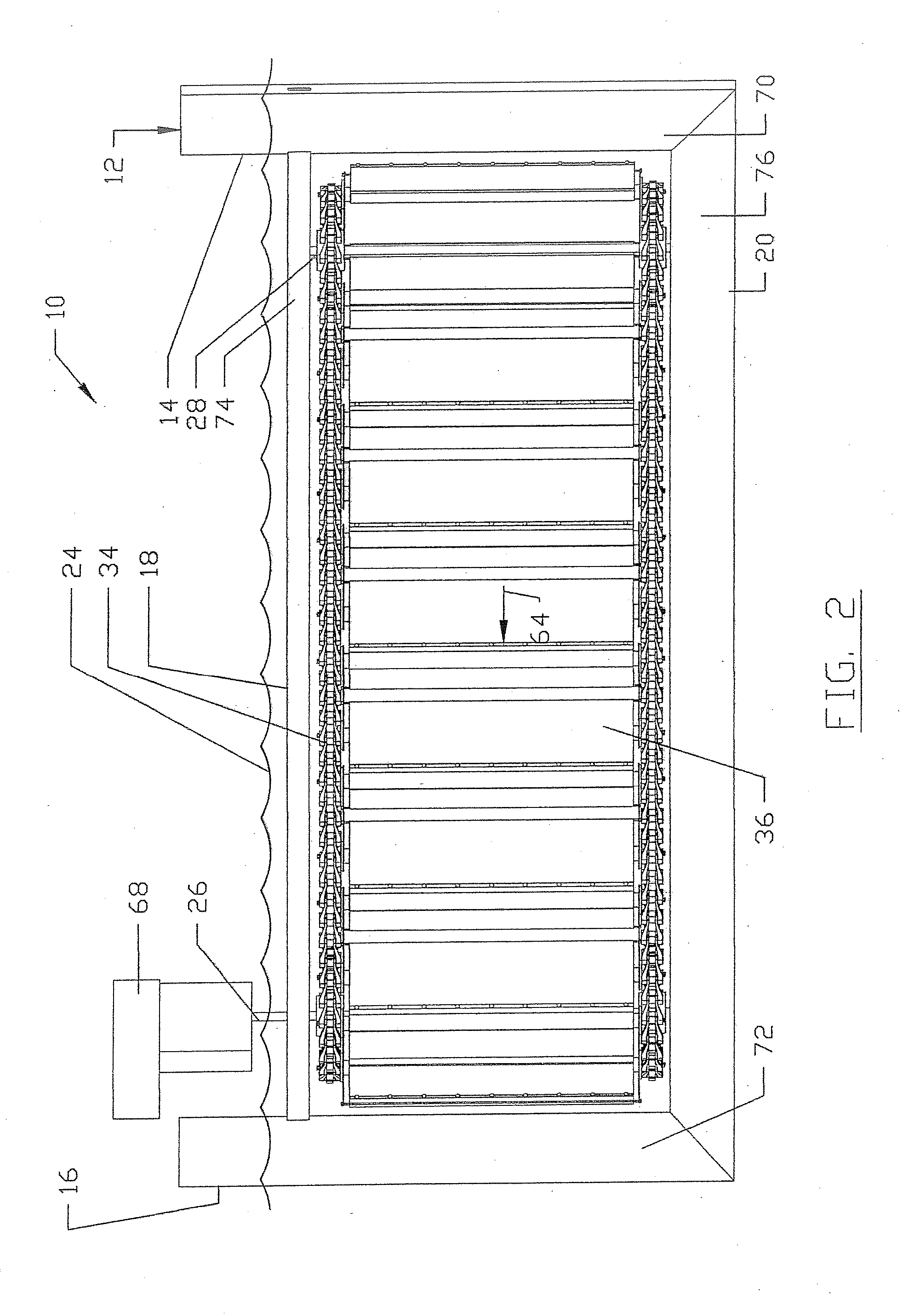
[0053]FIGS. 26-33 discloses a second example of apparatus 10 for harnessing energy from wind. Apparatus 10 includes support structure 162 used to support and guide upper and lower trolley trains 164 along a closed loop path 168. Trolley trains 164 include trolleys 170 with sail assemblies 172 mounted to and between the trolleys of the upper and lower trolley trains. Trolley trains 164 are preferably continuous loop trolley trains. Closed loop path 168 preferably has straight sections and curved sections with curved sections having radii sufficiently large to help reduce excessive friction and binding of the trolley trains 164. In one example and minimum radius of 10 feet (3 m) is preferred.

[0054] Referring now to FIGS. 27-30, trolley 170 is seen to include a roller 174 rotatably secured between roller supports 176. Adjacent trolleys 170 are secured to one another by a connector 178. Connector 178 includes end portions 180 rigidly secured to and between roller supports 176 by a pair...


PUM


Abstract

Apparatus for harnessing energy from wind comprises upper and lower continuous-loop trackways defining a continuous loop path and a series of connected, movable wind foils. Each wind foil has a leading edge mast engaging and guided by the upper and lower trackways. Each wind foil is movable between first and second orientations when moving along first and second portions of the path. A second example comprises a support structure having upper and lower closed loop trackways having inner and outer trackway rails and defining a closed loop path which guides a series of connected trolleys. Each trolley has a roller mounted to a roller support. The roller is guided by the rails of the upper and lower trackways. Sail assemblies each have a mast and a sail extending from the mast, with the upper and lower ends of the mast mounted to and supported by upper and lower trolleys.

Description

CROSS-REFERENCE TO OTHER APPLICATIONS [0001] This application claims the benefit of U.S. provisional patent application number 60 / 746,606, filed 5 May 2006, entitled FLUID ENERGY-HARVESTING APPARATUS. This application is related to International Application No. PCT / US 2004 / 028916 filed 3 Sep. 2004, published 16 Mar. 2006 as International Publication Number WO 2006 / 028454 A2, and entitled CONVEYOR-TYPE FLUID ENERGY-HARNESSING APPARATUS. This application is also related to U.S. Pat. No. 6,809,430 issued 26 Oct. 2004.STATEMENT REGARDING FEDERALLY SPONSORED RESEARCH OR DEVELOPMENT [0002] None. REFERENCE TO MICROFICHE APPENDIX [0003] None. BACKGROUND OF THE INVENTION [0004] The concept of harnessing energy from moving water and the wind continues to be the source of research and innovation. The most common method used to harness energy from moving water involves building a hydroelectric dam and extracting energy by passing water through turbines. Building dams creates problems, including...

Claims


Application Information

Patent Timeline
Patent Type & Authority Applications(United States)
IPC IPC(8): F03D9/00F03D5/02
CPCF03B17/066F03D5/02Y02E10/721Y02E10/28Y02E10/70F05B2240/311Y02E10/30Y02E10/20Y02E10/72
Inventor DIEDERICH, JURGEN
Owner DIEDERICH JURGEN
Features
  • Generate Ideas
  • Intellectual Property
  • Life Sciences
  • Materials
  • Tech Scout
  • Unparalleled Data Quality
  • Higher Quality Content
  • 60% Fewer Hallucinations
Learn More