Magnet switch with mechanism for preventing impact force imposed thereon

a technology of impact force and magnet switch, which is applied in the field of magnet switch, can solve the problems of reducing the size of the magnet switch, insulating the contact risk, and affecting the operation of the switch,

Inactive Publication Date: 2008-01-10
DENSO CORP
View PDF0 Cites 24 Cited by
  • Summary
  • Abstract
  • Description
  • Claims
  • Application Information

AI Technical Summary

Benefits of technology

[0021]The configuration described above may prevent suction of water to the side of the first columnar part of the plunger. The clearance between the outer peripheral surface of the second columnar part and the inner peripheral surface of the bobbin is larger than the clearance between the outer peripheral surface of the second columnar part and the end face of the projection. Accordingly, movement of the plunger toward the first core may ensure formation of a space on the side of the second core of the first columnar part, the space being larger than the space defined by the second columnar part and the projection. In this way, in case of the possible attachment of water droplets to the outer peripheral surface of the second columnar part by, for example, being submerged in water, air contained in this large space can prevent suction of water to the side of the first columnar part of the plunger.

Problems solved by technology

Upon imposition of the impact force, the movable contact may have a risk of being deformed or the insulator may have a risk of being broken.
However, the large thickness has necessitated the increase in the axial length of the magnet switch, raising a problem of difficulty in reducing the size of the magnet switch.

Method used


Image

  • Magnet switch with mechanism for preventing impact force imposed thereon
  • Magnet switch with mechanism for preventing impact force imposed thereon
  • Magnet switch with mechanism for preventing impact force imposed thereon

Examples


first embodiment

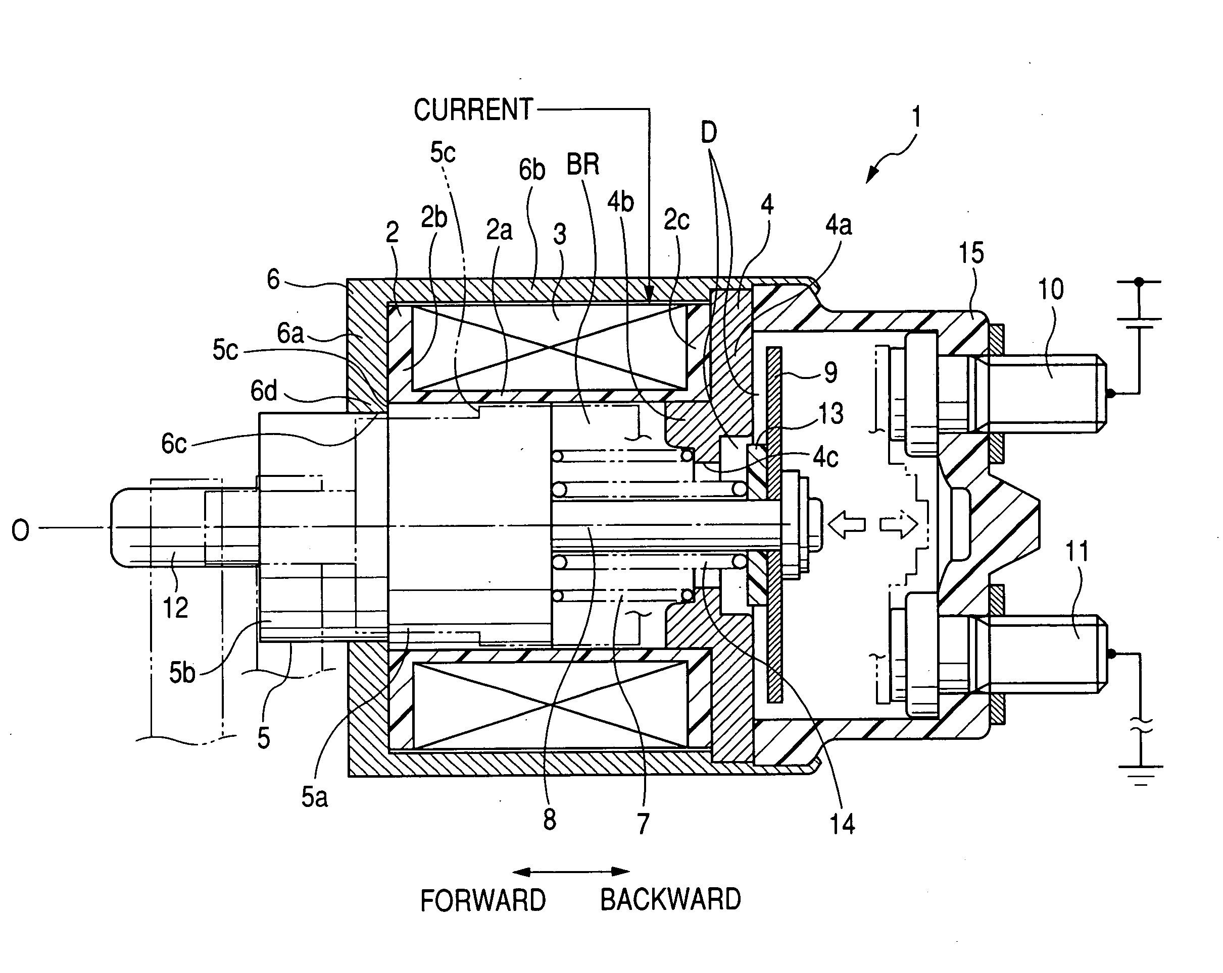
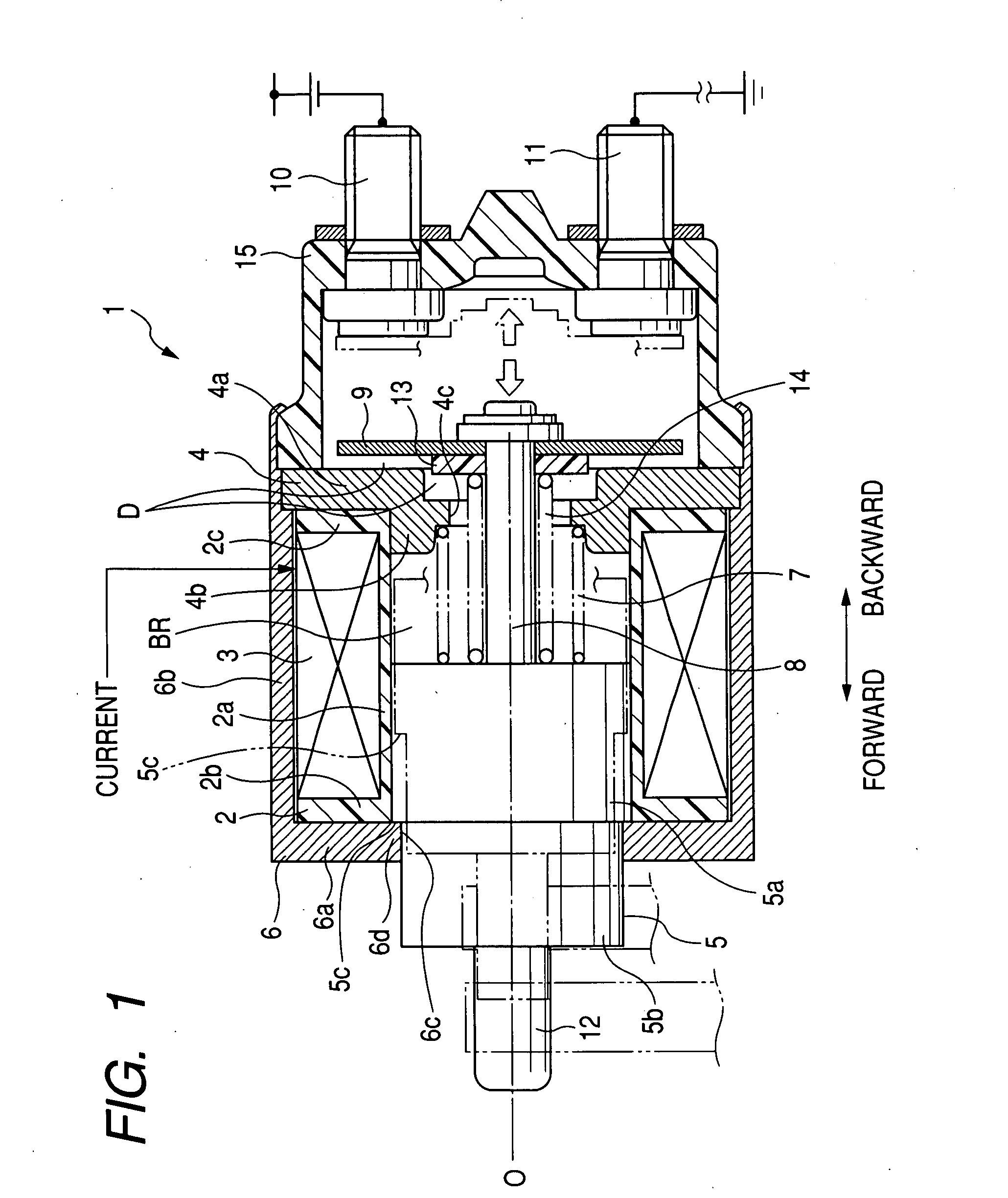
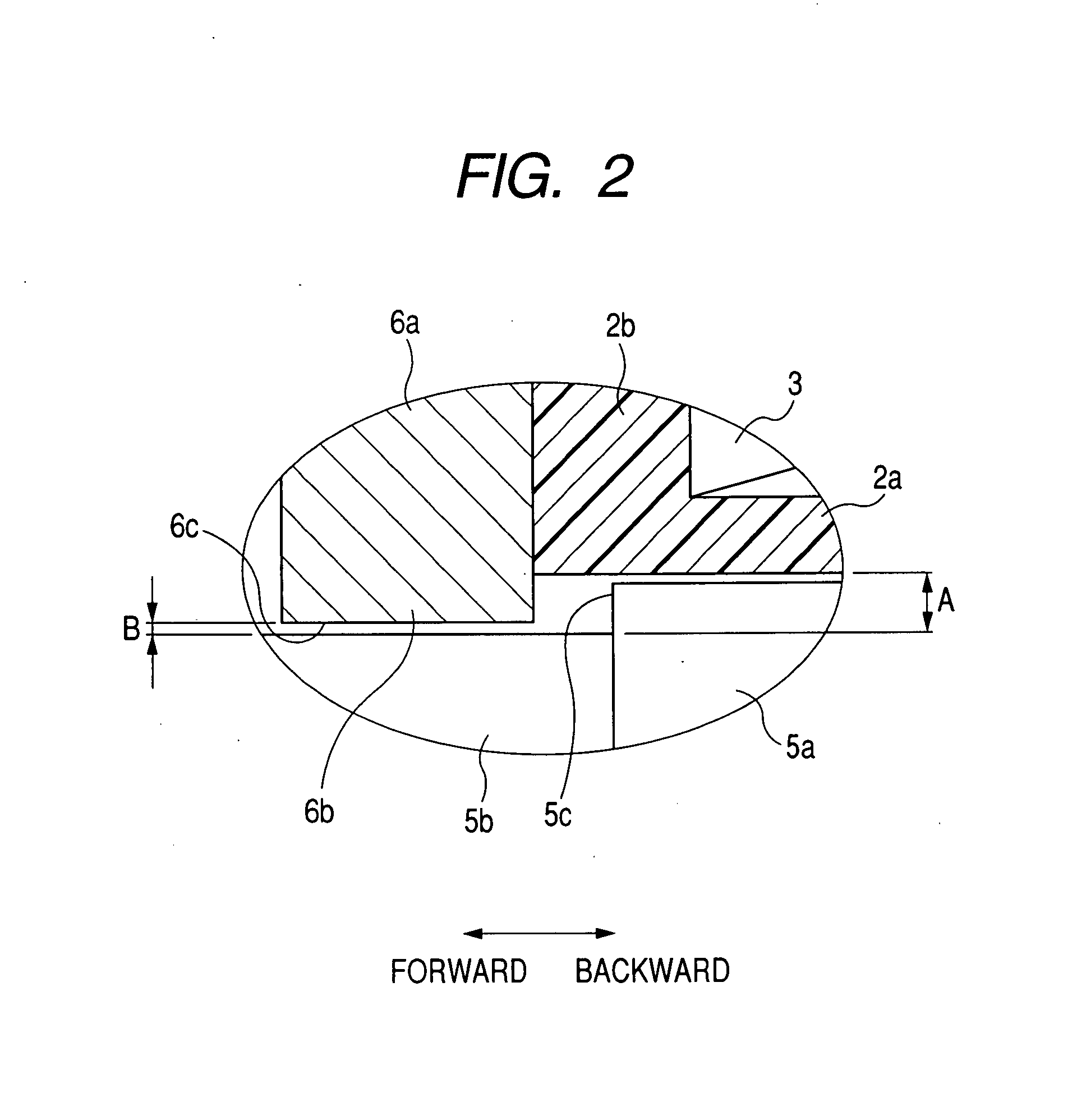
[0028]Referring to FIGS. 1 and 2, an explanation will be focused on a configuration of a starter magnet switch. FIG. 1 is a cross sectional view of a starter magnet switch, according to a first embodiment of the present invention. FIG. 2 is an enlarged cross sectional view in the vicinity of a stepped part of a plunger and a projection of a switch frame, according to the first embodiment.

[0029]As shown in FIG. 1, a starter magnet switch 1 (composing a magnet switch) includes a bobbin 2, an excitation coil 3 (coil), a stationary core 4 (composing a first core), a plunger 5, a switch frame 6 (composing a second core), a return spring 7 (composing a spring), a rod 8, a movable contact 9, and fixed contacts 10 and 11.

[0030]The bobbin 2, which holds the excitation coil 3, is a cylindrical member made of resin to provide insulation from other members. The bobbin 2 consists of a cylindrical part 2a and flange parts 2b and 2c formed at both end portions of the cylindrical part 2a. As shown ...

second embodiment

[0054]Hereinafter is described a starter magnet switch according to a second embodiment of the present invention. In the present embodiment, the identical or similar components to those in the first embodiment are given the same reference numerals for the sake of simplifying or omitting the explanation.

[0055]The starter magnet switch of the second embodiment is different from that of the first embodiment in that the projection formed at the switch frame in the first embodiment is formed at the bobbin.

[0056]With reference to FIGS. 3 and 4, a configuration of the starter magnet switch of the second embodiment will be described. FIG. 3 is a cross sectional view of the starter magnet switch according to the second embodiment. FIG. 4 is an enlarged cross sectional view in the vicinity of a stepped part of the plunger and a projection of the bobbin. Description here is focused only on the structures of the bobbin, the plunger and the switch frame, which make differences from the starter m...


PUM


Abstract

A magnet switch for a starter of the present invention includes a plunger and a switch frame. The plunger has a stepped part at the outer peripheral surface thereof. The switch frame has a projection at an end face thereof, the end face being opposed to the outer peripheral surface of the plunger. Engagement of the stepped part of the plunger with the projection of the switch frame can lock forward movement of the plunger, so that no impact force is imposed on the movable contact and the insulator. Thus, deformation of the movable contact and breakage of the insulator can be prevented, and the axial length of the magnet switch can be reduced to reduce the size of the magnetic switch.

Description

CROSS-REFERENCE TO RELATED APPLICATION[0001]This application is based on and claims the benefit of priority from earlier Japanese Patent Application No. 2006-185603 filed Jul. 5, 2006, the description of which is incorporated herein by reference.BACKGROUND OF THE INVENTION[0002]1. Technical Field of the Invention[0003]The present invention relates to a magnet switch for opening / closing a contact by a magnetic force. In particular, the present invention relates to a reduced-size magnet switch having a mechanism for preventing an impact force imposed on the magnetic switch to prevent damages caused therein, such as deformation of a movable contact or breakage of an insulator.[0004]2. Related Art[0005]A magnet switch for opening / closing a contact by a magnetic force is disclosed, for example, in Japanese Patent Laid-Open No. 3-000969 or a PCT pamphlet of WO00 / 26533.[0006]The magnetic switch disclosed in Japanese Patent Laid-Open No. 3-000969 includes a plunger, a movable contact attach...

Claims


Application Information

Patent Timeline
Patent Type & Authority Applications(United States)
IPC IPC(8): H01H75/10
CPCH01H51/065H01H50/20
Inventor ANDOH, KAZUHIROKURASAWA, TADAHIROUTSUNOMIYA, YAMATO
Owner DENSO CORP
Why Eureka
Try Eureka