Multiple-Set Heat-Dissipating Structure For LED Lamp

a technology of led lamps and heat dissipation structures, which is applied in the direction of lighting and heating apparatus, lighting heating/cooling arrangements, display means, etc., can solve the problems of insufficient heat dissipation, insufficient heat dissipation structure of conventional led lamps, and inevitable increase in heat generated by light-emitting diodes. , to achieve the effect of prolonging the li

Inactive Publication Date: 2008-01-10
JAFFE
View PDF14 Cites 71 Cited by
  • Summary
  • Abstract
  • Description
  • Claims
  • Application Information

AI Technical Summary

Benefits of technology

[0008]The present invention is to provide a multiple-set heat-dissipating structure for a LED lamp. By dispersing each heat pipe and heat-dissipating body, the heat generated by the operation of the LED set can be conducted and dissipated by each heat pipe and heat-dissipating body at multiple points. In this way, the LED set can be continuously operated under a suitable working temperature and thus its life can be elongated.

Problems solved by technology

However, with the subsequent development of increasing number of light-emitting diodes and high-power light-emitting diodes, the heat generated by the operation of the light-emitting diodes is inevitably increasing.
Therefore, it is an important issue for those skilled in this art to provide a heat-dissipating structure for LED lamps.
However, in practice, the conventional heat-dissipating structure for the LED lamp still has the following problems.
The region other than the middle portion of each heat-dissipating piece 22a only occupies a limited space and thus is insufficient for the heat dissipation of the LED set.
Therefore, in the above-mentioned heat-dissipating structure, the heat transferred by such structure is greatly restricted, so that the life of the light-emitting diodes in the LED set is reduced.

Method used


Image

  • Multiple-Set Heat-Dissipating Structure For LED Lamp
  • Multiple-Set Heat-Dissipating Structure For LED Lamp
  • Multiple-Set Heat-Dissipating Structure For LED Lamp

Examples


Embodiment Construction

[0020]The characteristics and the technical contents of the present invention will be described with reference to the following detailed description and the accompanying drawings. However, it should be understood that the drawings are illustrative but not used to limit the scope of the present invention.

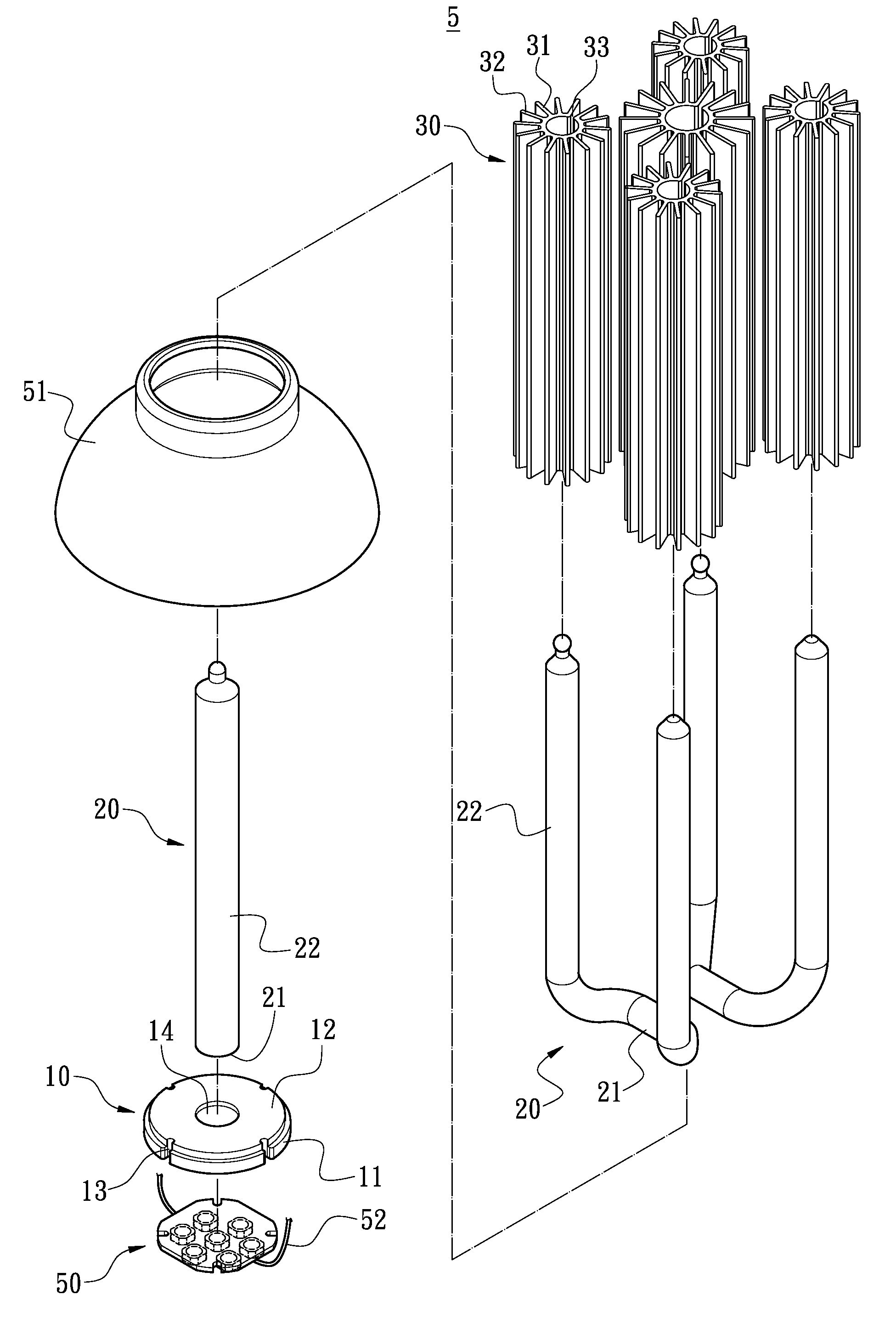
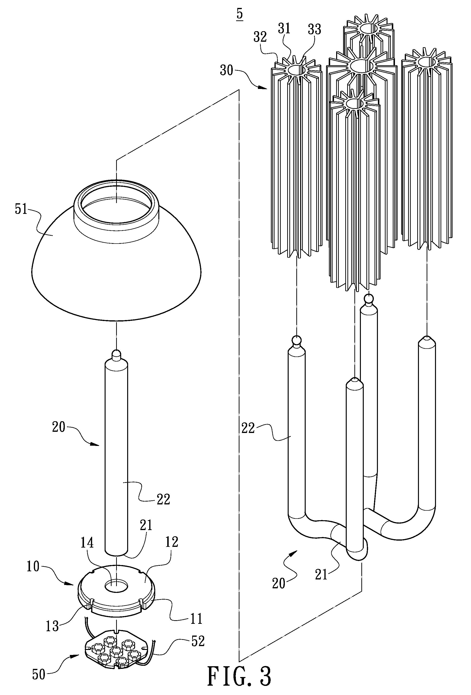
[0021]FIG. 3 is an exploded perspective view of the first embodiment of the present invention. FIG. 4 is an assembled perspective view of the first embodiment of the present invention. FIG. 5 is a longitudinal cross-sectional view showing the assembling of the first embodiment of the present invention. FIG. 6 is a cross-sectional view taken along the line 6-6 of FIG. 5. The present invention provides a multiple-set heat-dissipating structure for a LED lamp for performing the heat dissipation of the LED set 50, which comprises a heat-conducting base 10, a plurality of heat pipes 20 and a plurality of heat-dissipating bodies 30.

[0022]The heat-conducting base 10 can be made of aluminum,...


PUM


Abstract

A multiple-set heat-dissipating structure for a LED lamp for performing the heat dissipation of the LED set includes a heat-conducting base, a plurality of heat pipes and a plurality of heat-dissipating bodies. On end face of the heat-conducting base is used for adhering to and contacting with the LED set. Each heat pipe has a heat-absorbing end and a heat-releasing end, respectively. The heat-absorbing end is connected to the other end face of the heat-conducting base. Each heat-dissipating body has a hollow cylinder. The outer periphery of the cylinder is formed with a plurality of radial heat-dissipating pieces and is connected on the heat-releasing end of each heat pipe. By dispersing each heat pipe and heat-dissipating body, the heat generated by the operation of the LED set can be conducted and dissipated by each heat pipe and heat-dissipating body at multiple points. In this way, the LED set can be continuously operated under a suitable working temperature and thus its life can be elongated.

Description

BACKGROUND OF THE INVENTION[0001]1. Field of the Invention[0002]The present invention relates to a multiple-set heat-dissipating structure for a LED lamp, and in particular to a multiple-set heat-dissipating structure for performing the heat dissipation of the LED lamp.[0003]2. Description of Prior Art[0004]Since light-emitting diodes (LED) are high-intensity, energy-saved and long-life, they are widely used in the illumination of electronic devices or lamps. Further, in order to increase the illuminating range and intensity thereof, a plurality of light-emitting diodes are usually combined to form a LED set. However, with the subsequent development of increasing number of light-emitting diodes and high-power light-emitting diodes, the heat generated by the operation of the light-emitting diodes is inevitably increasing. Therefore, it is an important issue for those skilled in this art to provide a heat-dissipating structure for LED lamps.[0005]As shown in FIGS. 1 and 2, the convent...

Claims


Application Information

Patent Timeline
Patent Type & Authority Applications(United States)
IPC IPC(8): F21V29/00
CPCF21V29/004F21V29/006F21V29/773Y10S362/80F21V29/717F21Y2101/02F21V29/51F21Y2115/10
Inventor LI, JIA-HAO
Owner JAFFE
Why Eureka
Try Eureka