
Image compression based on union of DCT and wavelet transform

a wavelet transform and image compression technology, applied in the field of digital image data compression, can solve the problems of severely reducing coding efficiency, scan pattern cannot effectively exploit the 2-dimensionally distributed statistical dependency, etc., and achieve the effect of improving image compression performan

Inactive Publication Date: 2008-01-10
LIU XITENG
View PDF0 Cites 22 Cited by
  • Summary
  • Abstract
  • Description
  • Claims
  • Application Information

AI Technical Summary

Benefits of technology

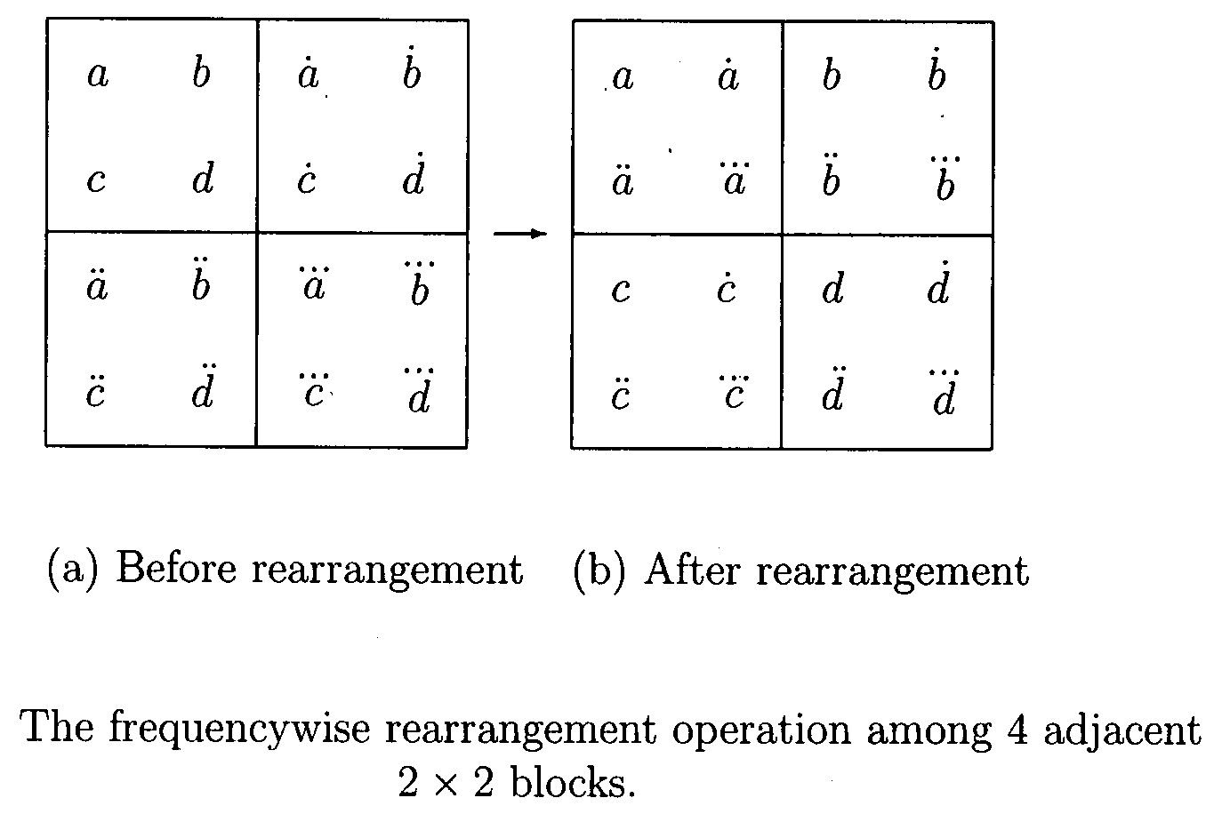
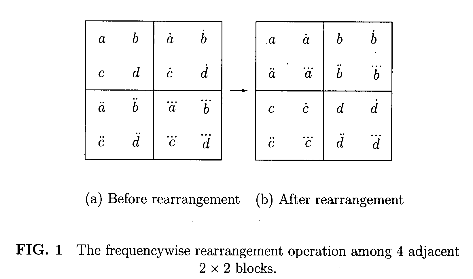
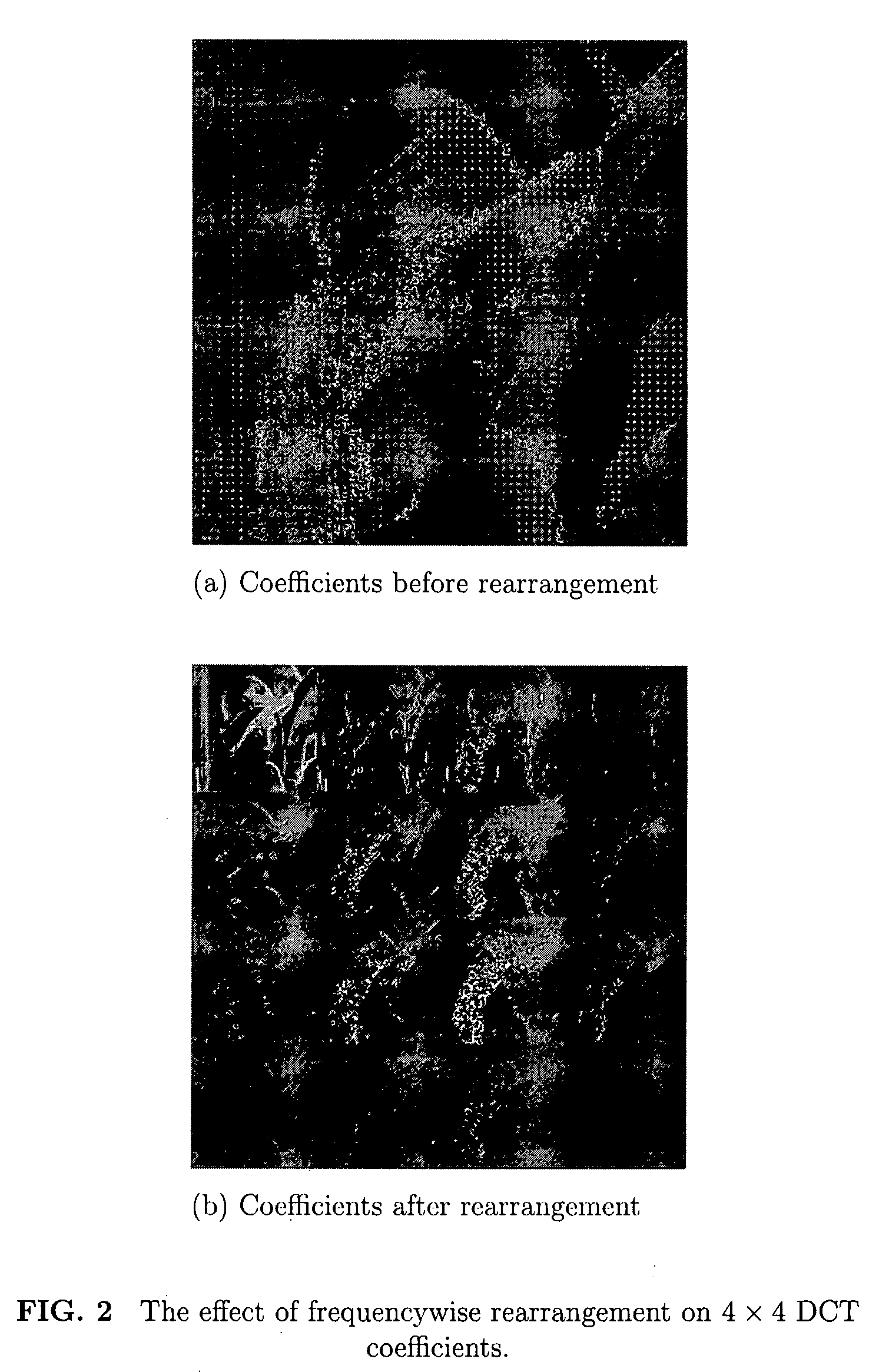
[0003]To effectively exploit the statistical dependency between the local frequency contents of image signals and hence greatly improve image compression performance, one method and apparatus described in the present invention involves rearranging block-based DCT coefficients into a number of frequency groups and then decomposing one or more of those groups by wavelet transform. Initially, the original image data are partitioned into blocks, say, 4×4 or 8×8. The blocks of data are decomposed by DCT (Discrete Cosine Transform) or integer approximants to DCT or Hadamard transform. Afterward, the DCT coefficients are rearranged into a number of groups such that the coefficients locating at the same coordinate within all transform blocks are in one group. The number of groups is equal to the size of transform block. The coordinate of a coefficient within a group is the coordinate of the block (which the coefficient comes from) within the whole image domain. Then, one or more groups are decomposed by discrete wavelet transform. At least, the DC group, i.e. the group of coefficients at coordinate (0, 0), is decomposed further by wavelet transform.

Problems solved by technology

The linear scan patterns can not effectively exploit the 2-dimensionally distributed statistical dependency and hence severely reduce coding efficiency.

Method used


Image

  • Image compression based on union of DCT and wavelet transform
  • Image compression based on union of DCT and wavelet transform
  • Image compression based on union of DCT and wavelet transform

Examples


Embodiment Construction

[0011]One apparatus and method for effectively exploiting the statistical dependency between local frequency contents of image signals and hence greatly improving compression performance in an image compression system is herein disclosed. In the following description, for the purpose of explanation, specific nomenclature and specific implementation details are set forth to provide a full understanding of the present invention. The details of the techniques are apparent for one skilled in the art to practice the present invention.

[0012]Frequencywise Rearrangement of DCT Coefficients

[0013]The block-based discrete cosine transform (DCT) or its integer approximant is extensively applied in image or video coding systems, including JPEG, MPEG1, MPEG2, MPEG4, H.263 and H.264. It helps to decompose the image data into DCT coefficients which reflects the local frequency contents of the image signal. In those systems, DCT coefficients are scanned and encoded in a linear zigzag patter. However...


PUM


Abstract

A union of DCT (discrete cosine transform) and wavelet transform can generate a much sparser representation of the digital image signal than either of them alone. After the block-based DCT, the coefficients are rearranged into a number of frequency groups such that the coefficients locating at the same coordinate in all transform blocks are in one group. Then, one or more such groups are further decomposed by wavelet transform. After quantization, each frequency group is divided into squares. The squares are identified and encoded as either all-zero or not-all-zero. Inside those not-all-zero squares, the coefficients are encoded bit-plane by bit-plane in a 2-dimensional quaternary reaching pattern. Compared to existing peer systems, the compression performance is improved up to 30%, especially in high quality cases. For lossless compression, the image data is decomposed by a union of a reversible DCT approximant and a reversible wavelet transform. Besides, the coefficients are quantized by a remnant-preserved, partial quantization scheme. The lossless compression performance is improved about 20% against JPEG2000.

Description

FIELD OF THE INVENTION[0001]The present invention relates to digital image data compression.BACKGROUND OF THE INVENTION[0002]In existing digital image and video data compression systems, such as JPEG, JPEG2000, MPEG1, MPEG2, MPEG4 and H.264, single mathematical transform is used. Among them, JPEG, MPEG1, 2, 4 and H.264 adopt the discrete cosine transform (DCT) or an integer approximant to DCT (H.264). JPEG2000 adopts the discrete wavelet transform. In all existing DCT-based image / video coding systems, the transform coefficients within a transform block are scanned and encoded in the famous linear zigzag pattern. In JPEG2000, the wavelet coefficients within one code-block are scanned and encoded in a one-by-one, column-by-column pattern. However, image signals and video frame signals are 2-dimensional in nature. Besides, there is strong statistical dependency between the frequency contents of neighboring blocks of image signals. The linear scan patterns can not effectively exploit th...

Claims


Application Information

Patent Timeline
IPC IPC(8): G06K9/36H04N7/12
CPCH04N19/176H04N19/63H04N19/184H04N19/60H04N19/18H04N19/122
Inventor LIU, XITENG
Owner LIU XITENG
Learn More