Brake system, stroke simulator disconnecting mechanism, and stroke simulator disconnecting method
- Summary
- Abstract
- Description
- Claims
- Application Information
AI Technical Summary
Benefits of technology
Problems solved by technology
Method used
Image

Examples
first embodiment
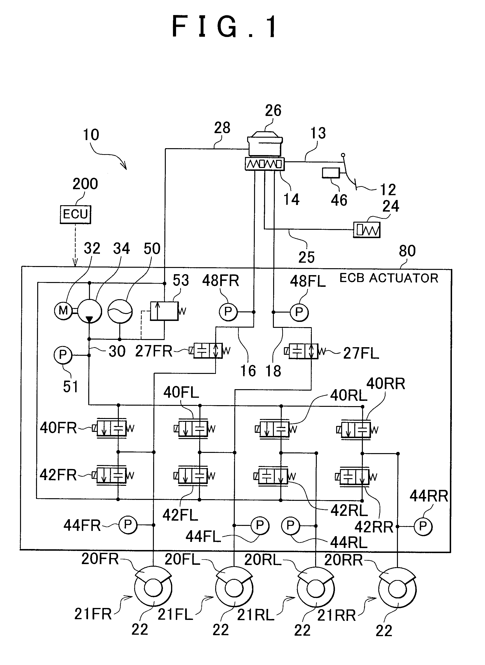
[0034]In each of the disc brake units 21FR to 21RL, when brake fluid is supplied to the wheel cylinders 20 from the ECB actuator 80, a brake pad, which is a friction member, is pressed against each of the brake discs 22, so that a braking force is applied to the wheel of the vehicle. While the disc brake units 21FR to 21RL are employed in the first embodiment, other braking force applying devices that use wheel cylinders, such as drum brake units, may alternatively be employed, or braking force applying devices that use electric actuators, such as electric motors, to control the pressures with which the friction members of the respective brakes are pressed against the wheels of the vehicle, rather than using hydraulic systems or devices, may alternatively be employed.
[0035]The brake pedal 12 is connected to a master cylinder 14 that pressurizes and discharges brake fluid, which is hydraulic fluid, in response to the brake pedal 12 being stepped down by the driver of the vehicle. The...
second embodiment
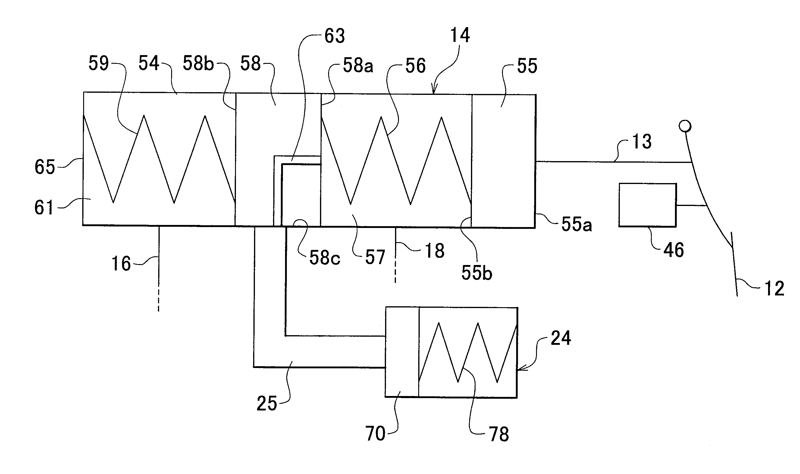
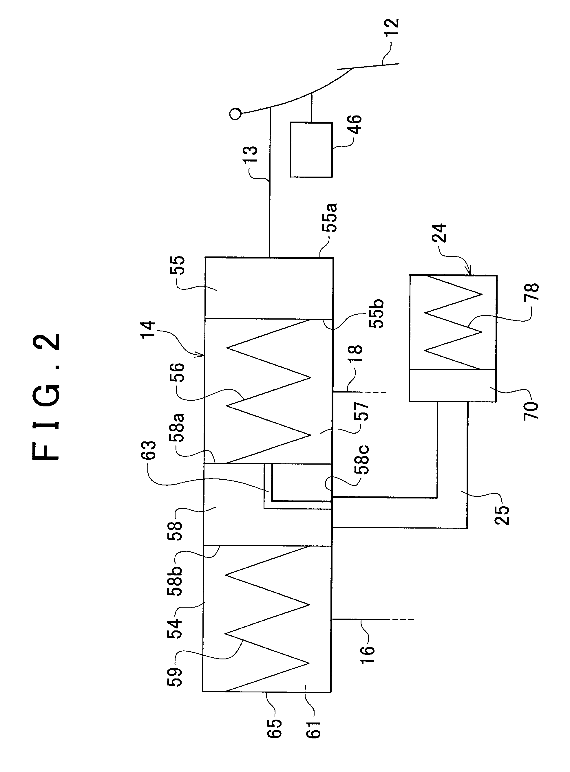
[0093]When the load acting on the first master piston 55 exceeds the mounting load of the first master spring 56 as the brake pedal 12 is depressed, the first master spring 56 starts to be compressed. At this time, the first master piston 55 starts sliding and the link rod 104 starts to be inserted into the in-piston passage 63 of the second master piston 58. In the second embodiment, the in-piston passage 63 accommodates the link rod 104 when the first master piston 55 is sliding. As the first master piston 55 slides, the brake fluid flows into the in-piston passage 63 via the hole 110 and then to the stroke simulator 24.
[0094]As described above, in the second embodiment, the mounting load of the first master spring 56 is maintained by the linking member 98, and therefore the mounting load of the first master spring 56 and the mounting load of the second master spring 59 can be made different from each other. In general, even if an interconnected-spring structure is employed, the m...
third embodiment
[0103]In region B, the travel of the second master piston 58 increases as the travel of the brake pedal 12 increases, while the travel of the first master piston 55 remains unchanged despite the increase of the travel of the brake pedal 12. In region B, the load acting on the first master spring 56 and the second master spring 59 is larger than the mounting load of the second master spring 59, and therefore the first master spring 56 and the second master spring 59 are both elastically deformable. However, because the spring constant of the first master spring 56 is set much larger than the spring constant of the second master spring 59 in the third embodiment, mainly the second master spring 59 elastically deforms and the travel of the second master piston 58 increases as the travel of the brake pedal 12 increases.
[0104]Thus, the mounting load of the second master spring 59 is set smaller than the load that occurs at a point of the travel of the brake pedal 12 at which a brake requ...
PUM
 Abstract
Description
Claims
Application Information
 - R&D
- Intellectual Property
- Life Sciences
- Materials
- Tech Scout
- Unparalleled Data Quality
- Higher Quality Content
- 60% Fewer Hallucinations
Browse by: Latest US Patents, China's latest patents, Technical Efficacy Thesaurus, Application Domain, Technology Topic, Popular Technical Reports.
© 2025 PatSnap. All rights reserved.Legal|Privacy policy|Modern Slavery Act Transparency Statement|Sitemap|About US| Contact US: help@patsnap.com