Trailer brake system

Active Publication Date: 2008-03-20
WABCO EURO BVBA SPRL
View PDF5 Cites 26 Cited by
  • Summary
  • Abstract
  • Description
  • Claims
  • Application Information

AI Technical Summary

Benefits of technology

[0006]Generally speaking, it is an object of the present invention to provide a trailer brake system that overcomes the disadvantages of con

Problems solved by technology

Consequently, the electronic control function corresponding to the automatic brake signal, an example being a vehicle rollover prevention function, cannot be completely effective.
Also, with th

Method used


Image

  • Trailer brake system
  • Trailer brake system
  • Trailer brake system

Examples


Embodiment Construction

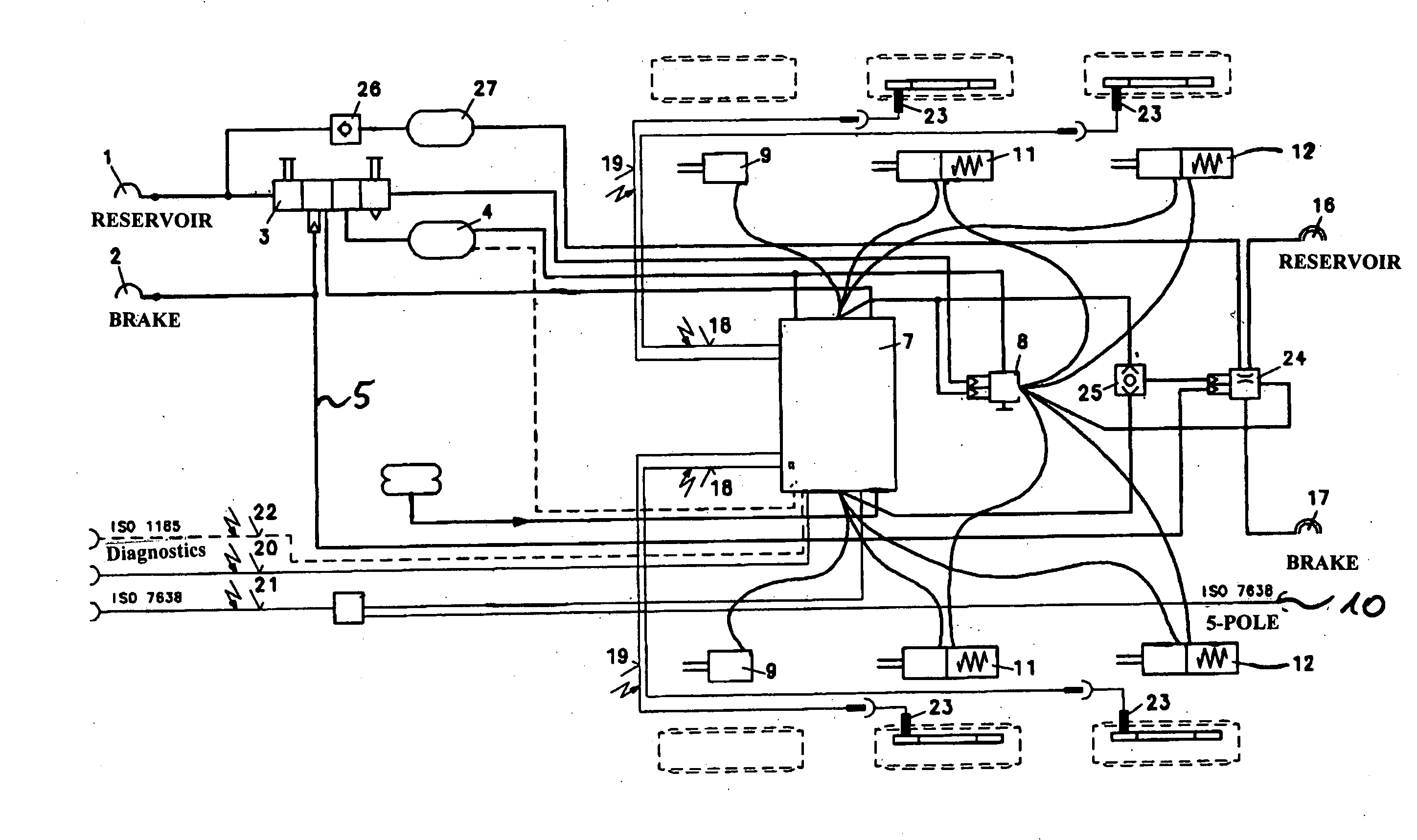
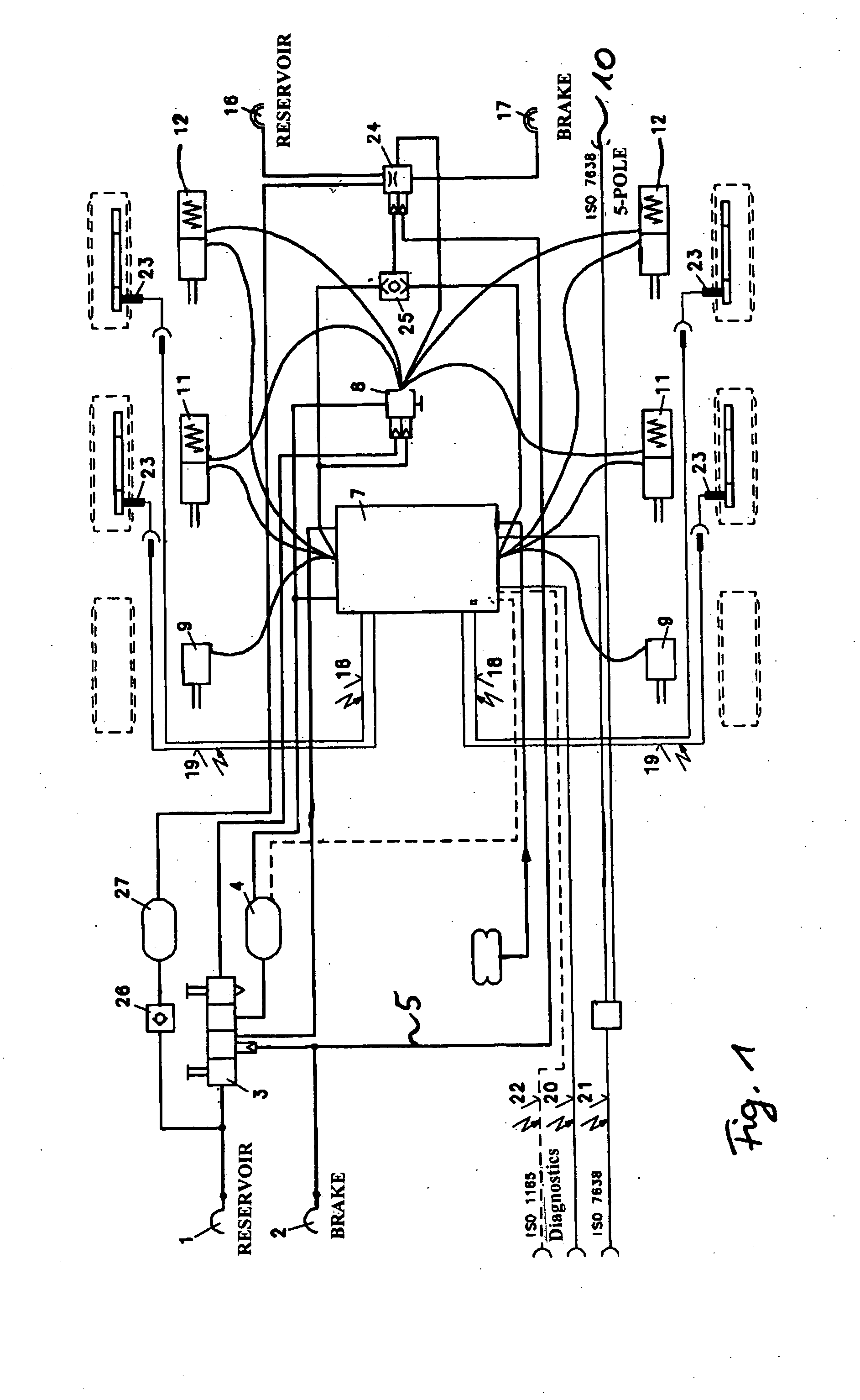
[0016]Referring to the drawing figures, where like reference numerals are used for corresponding parts, the trailer brake system in accordance with an embodiment of the present invention depicted in FIG. 1 is provided with a reservoir coupling head 1 and a brake coupling head 2. Coupling heads 1, 2 are used for connection to corresponding pressurized fluid ports of the vehicle tractor.

[0017]Via reservoir coupling head 1, a reservoir pressure of the tractor is injected into the brake system of the trailer. This reservoir pressure is guided via a check valve 26 to a compressed air reservoir tank 27 of the trailer.

[0018]The pressure of reservoir coupling head I is further guided to a combined park / release safety valve 3. The park / release safety valve 3 is used for manual control of the vehicle parking brake function or for releasing the parking brake in emergencies. Valve 3 is further used as a trailer brake valve with break safeguard, meaning that automatic braking of the trailer is i...


PUM


Abstract

A trailer brake system constructed and arranged to effect the relay of a brake signal from the tractor and an automatically generated brake signal of an electronic control device of the trailer to one or more additional trailers in an expanded vehicle train. In one embodiment, the brake signal is relayed to an additional coupled trailer in the form of an electrical signal via an electrical interface. In another embodiment, the brake signal is relayed to an additional trailer by means of a valve device. In yet another embodiment, the brake signal is relayed to an additional trailer by means of a combination of electrical signal transmission and valve device.

Description

BACKGROUND OF THE INVENTION[0001]The present invention relates generally to an improved trailer brake system for an expanded vehicle train including a tractor and multiple trailers, such as, for example, semitrailers or drawbar trailers, coupled in series thereto.[0002]A brake system of the general type under consideration is described in EP 1188634 A2. In the conventional brake system described in EP 1188634 A2, an electronic control device is provided that is capable of, among other things, preventing wheel lock or apportioning braking force as a function of axle load.[0003]Also, the electronic control device can generate an automatic brake signal, even without brake actuation by the vehicle train operator, to brake individual vehicle wheels or all wheels to effect handling stability control or prevent rollover of the vehicle train about its longitudinal axis.[0004]Furthermore, for braking an additional trailer coupled to the first or preceding trailer to form an expanded vehicle ...

Claims


Application Information

Patent Timeline
IPC IPC(8): B60T13/00
CPCB60T7/20B60T8/323B60T13/665B60T13/662B60T8/327
Inventor PARROTT, THOMASSTENDER, AXELTHA, INGO
Owner WABCO EURO BVBA SPRL
Why Eureka
Try Eureka