System for erecting ladder stand for hunting

a ladder stand and ladder technology, applied in the field of ladder stands, can solve the problems of difficult erecting of conventional ladder stands, and achieve the effect of stable support and easy movement of ladders

Inactive Publication Date: 2008-01-17
LOTT CHRIS
View PDF15 Cites 13 Cited by
  • Summary
  • Abstract
  • Description
  • Claims
  • Application Information

AI Technical Summary

Benefits of technology

[0007]A system for erecting a ladder stand for hunting has a pivoting base assembly connected to a bottom end of a ladder, and a pair of support legs pivotally attached to respective sides of an upper section of the ladder. The pivoting base assembly includes first and second foot pad members, anchoring stakes for anchoring the foot pad members to the ground, and a base frame pivotally connected to the foot pad members with a connection that allows level adjustment to accommodate uneven terrain. First and second receiver tubes are connected to the base frame for receiving the bottom end of the ladder. A spacing between the receiver tubes is adjustable to accommodate different ladder sizes. The pivoting base assembly receives and anchors the bottom end of the ladder and allows the ladder to be easily moved from a horizontal position to an upright position. The base assembly is substantially wider than the ladder to provide a more stable support for the ladder. The support legs have ground pegs at their lower ends for engaging the ground to support the ladder stand in an intermediate position as the ladder stand is being erected. The support legs also serve as handles for moving the stand from its intermediate position to its upright position.

Problems solved by technology

Conventional ladder stands are difficult to erect in the field and often require two people to complete the task.

Method used


Image

  • System for erecting ladder stand for hunting
  • System for erecting ladder stand for hunting
  • System for erecting ladder stand for hunting

Examples


Embodiment Construction

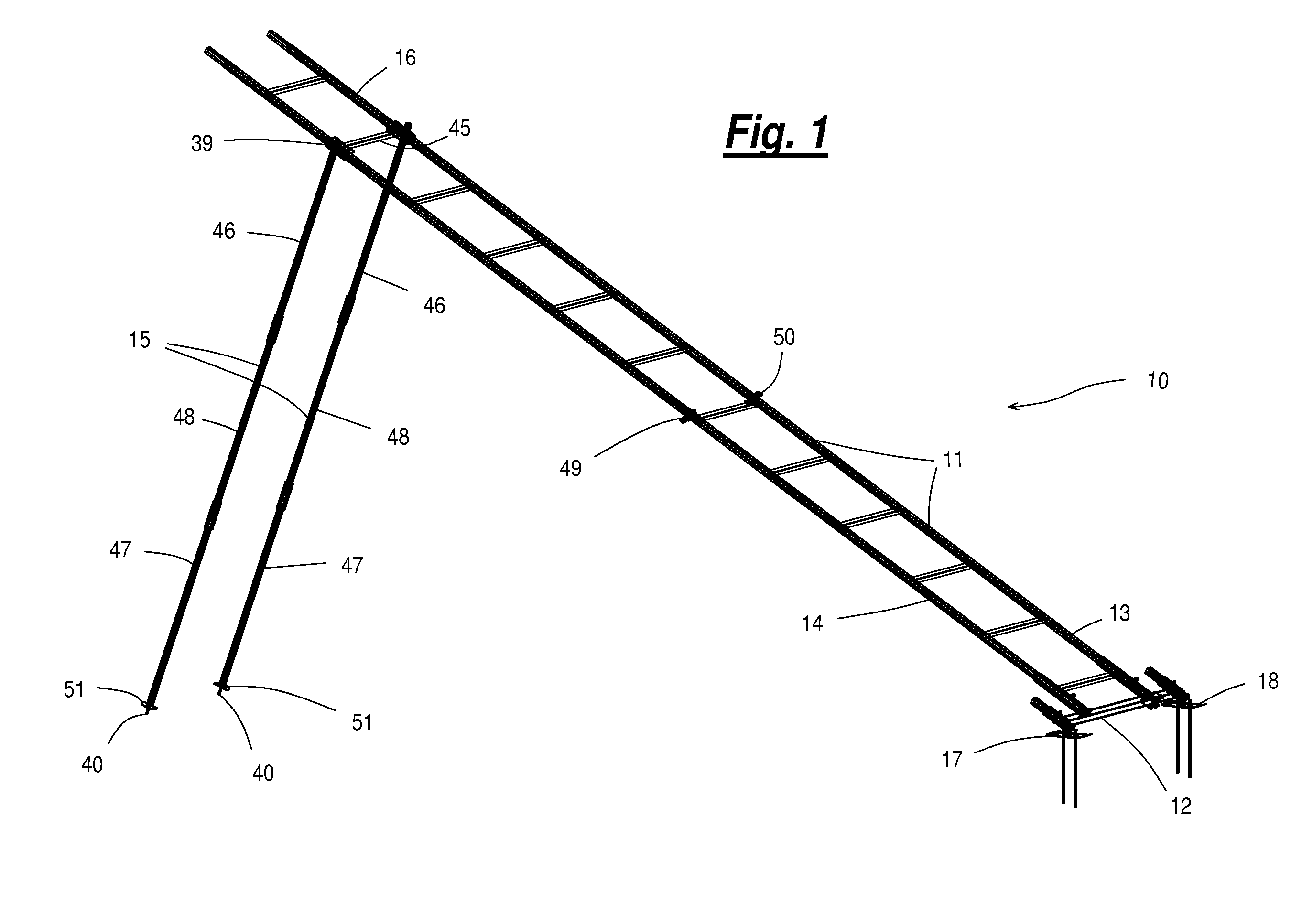
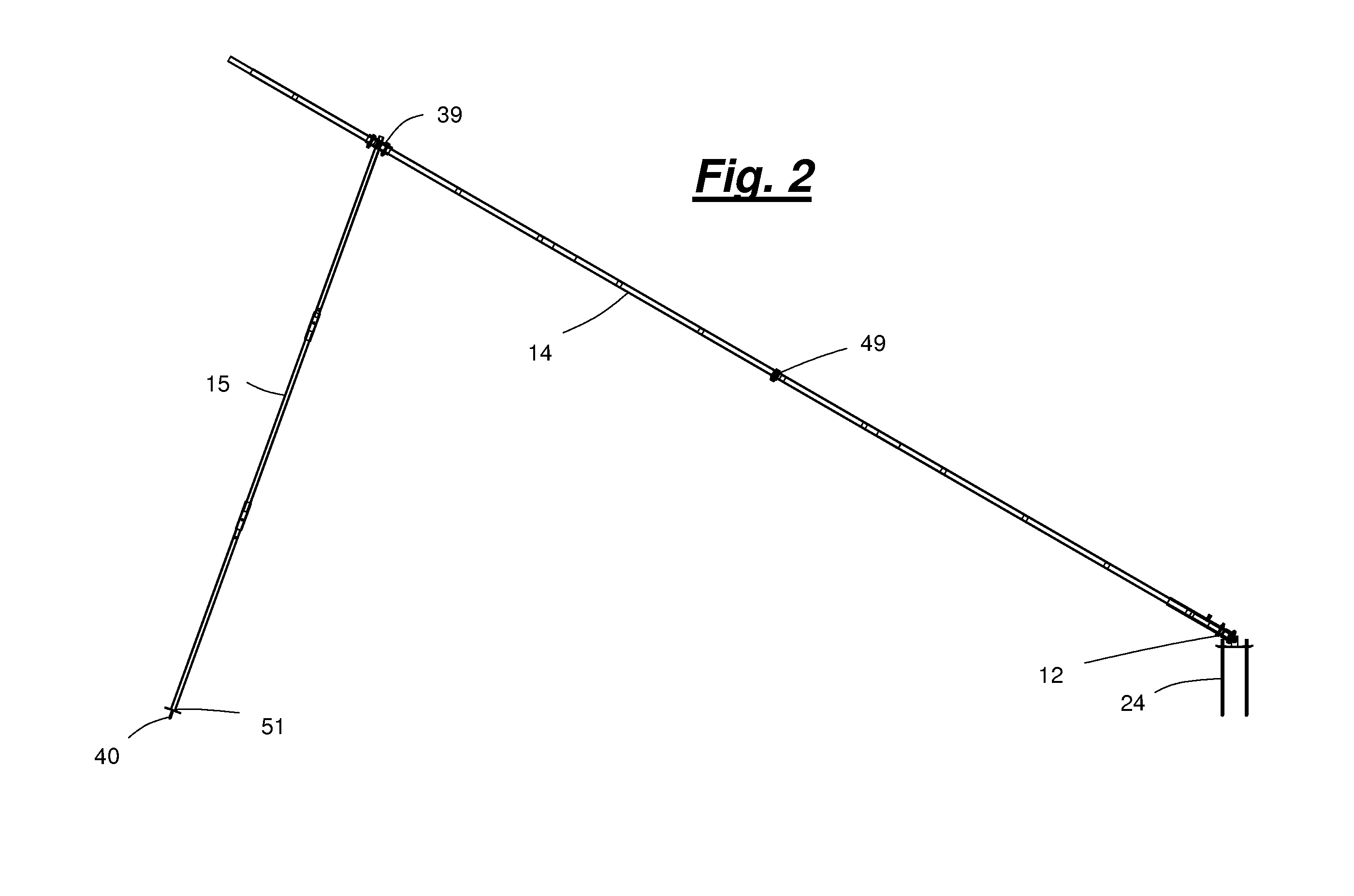
[0024]A system for erecting ladder stands for hunting according to the present invention will now be described in detail with reference to FIGS. 1 to 11 of the accompanying drawings.

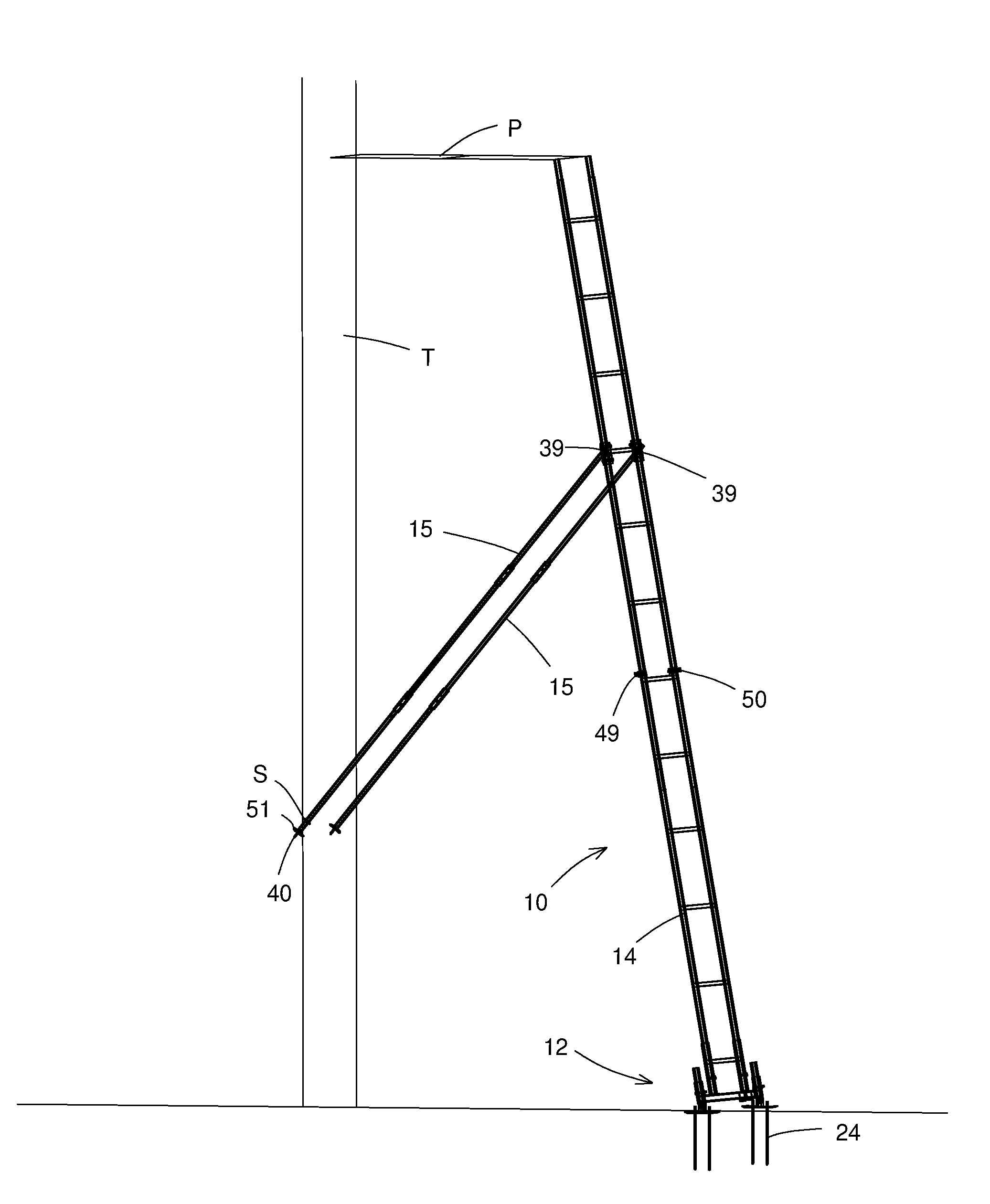
[0025]The present invention provides a system 10 for erecting a ladder stand 11 for hunting. The system 10 has been developed as an add-on accessory for use with existing ladder stands and has features that allow it to be adapted to various sizes and styles of existing ladder stands. However, it will be appreciated by those skilled in the art that some of the core concepts of the present invention can be built into new ladder stands as OEM features to provide improvements over existing techniques and products used to erect ladder stands.

[0026]The system 10 has two main components: a pivoting base assembly 12 adapted to be connected to a bottom end 13 of a ladder 14; and a pair of support legs 15 pivotally attached to respective sides of an upper section 16 of the ladder 14. Each of these components 12, 1...


PUM


Abstract

A system for erecting a ladder stand for hunting has a pivoting base assembly connected to a bottom end of a ladder, and a pair of support legs pivotally attached to respective sides of an upper section of the ladder. The pivoting base assembly includes first and second foot pad members, anchoring stakes for anchoring the foot pad members to the ground, a base frame pivotally connected to the foot pad members, and first and second receiver tubes connected to the base frame for receiving the bottom end of the ladder. The pivoting base assembly receives and anchors the bottom end of the ladder and allows the ladder to be easily moved from a horizontal position to an upright position. The support legs have ground pegs at their lower ends for engaging the ground to support the ladder stand in an intermediate position as the ladder stand is being erected.

Description

RELATED APPLICATIONS[0001]This application claims priority of U.S. Provisional Application No. 60 / 830,934 filed on Jul. 14, 2006. The content of this prior application is incorporated herein by reference.BACKGROUND OF THE INVENTION[0002]1. Field of the Invention[0003]The present invention relates generally to ladder-type tree stands for supporting hunters above the ground and, in particular, to systems and methods to facilitate erecting such ladder stands in the field.[0004]2. Description of the Related Art[0005]Ladder stands for hunting are well known and widely used by hunters. Such ladder stands typically comprise a ladder having a bottom end supported on the ground, and a platform supported at the top of the ladder and abutted against the tree. The ladder extends from the ground to the platform to allow the hunter to climb up to the platform.[0006]Conventional ladder stands are difficult to erect in the field and often require two people to complete the task. A system is needed ...

Claims


Application Information

Patent Timeline
Patent Type & Authority Applications(United States)
IPC IPC(8): E06C1/04E06C7/10E06C7/42
CPCE06C7/42E06C7/46E06C7/423
Inventor LOTT, CHRIS
Owner LOTT CHRIS
Why Eureka
Try Eureka