Multiposition angle valve

a multi-angle, valve technology, applied in the direction of valve operating means/releasing devices, functional valve types, mechanical devices, etc., can solve the problems of bellows replacement, material and process fabrication,

Inactive Publication Date: 2008-01-17
HIGH VACUUM APP MFG
View PDF9 Cites 11 Cited by
  • Summary
  • Abstract
  • Description
  • Claims
  • Application Information

AI Technical Summary

Benefits of technology

[0016] The stop assembly may include a support rod extending into the piston chamber, a stop piston carried on a lower end of the support rod and housed in the piston chamber and independent of the drive piston, and a knob adjustably secured to the support rod along a portion thereof outside of the piston chamber. The knob may be configured for adjustably limiting the downward movement of the stop assembly. The knob may be threaded to the support rod.
[0017] In one embodiment, the angle valve includes a first pressure source configured for applying downward first pressure to the drive piston to move the driveshaft to a closed position. A second pressure source may be configured for applying downward second pressure to the stop piston to move the stop piston to a stop position. A third pressure source may be configured for applying an upward third pressure to the drive piston to move the drive piston upwardly. The angle valve may be in a partial-open position when there may be a positive pressure differential in which the second pressure exceeds a third pressure thereby causing the drive piston to abut against the stop piston in the stop position. The partial-open position may be defined by a pressure differential between the stop assembly and valve driveshaft such that the stop assembly may be in a lowered position and abutting the piston plug.

Problems solved by technology

The sensitive nature of the fabrication materials and processes typically requires minimization of contaminants.
While such configuration has proven adequate, such configuration often requires replacement of the bellows every 300,000 cycles.
Therefore, all the components connected to the cluster assemblies desirably limit the frequency of repair and replacement, which contribute to downtime.

Method used


Image

  • Multiposition angle valve
  • Multiposition angle valve
  • Multiposition angle valve

Examples


Embodiment Construction

[0026] Reference will now be made in detail to the preferred embodiments of the invention, examples of which are illustrated in the accompanying drawings. While the invention will be described in conjunction with the preferred embodiments, it will be understood that they are not intended to limit the invention to those embodiments. On the contrary, the invention is intended to cover alternatives, modifications and equivalents, which may be included within the spirit and scope of the invention as defined by the appended claims.

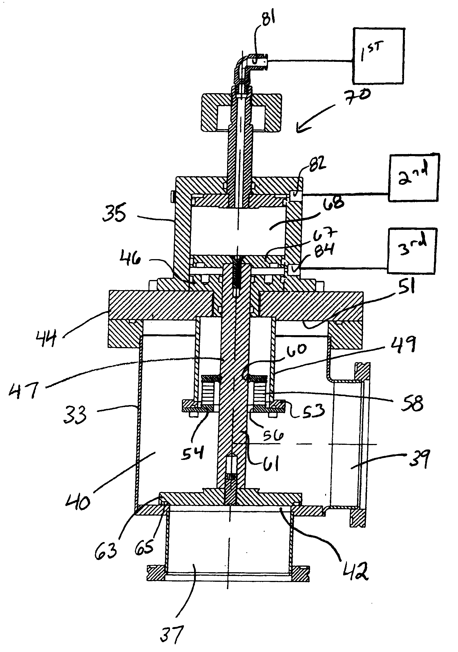
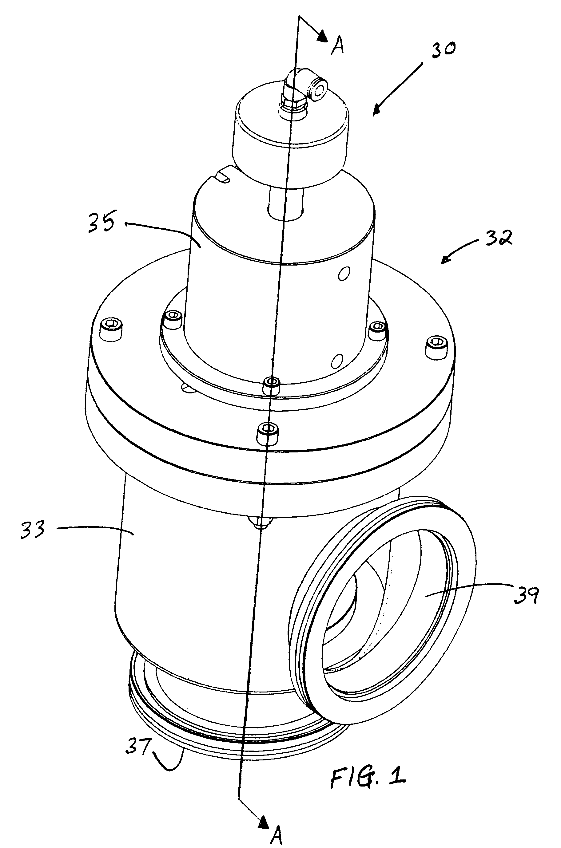
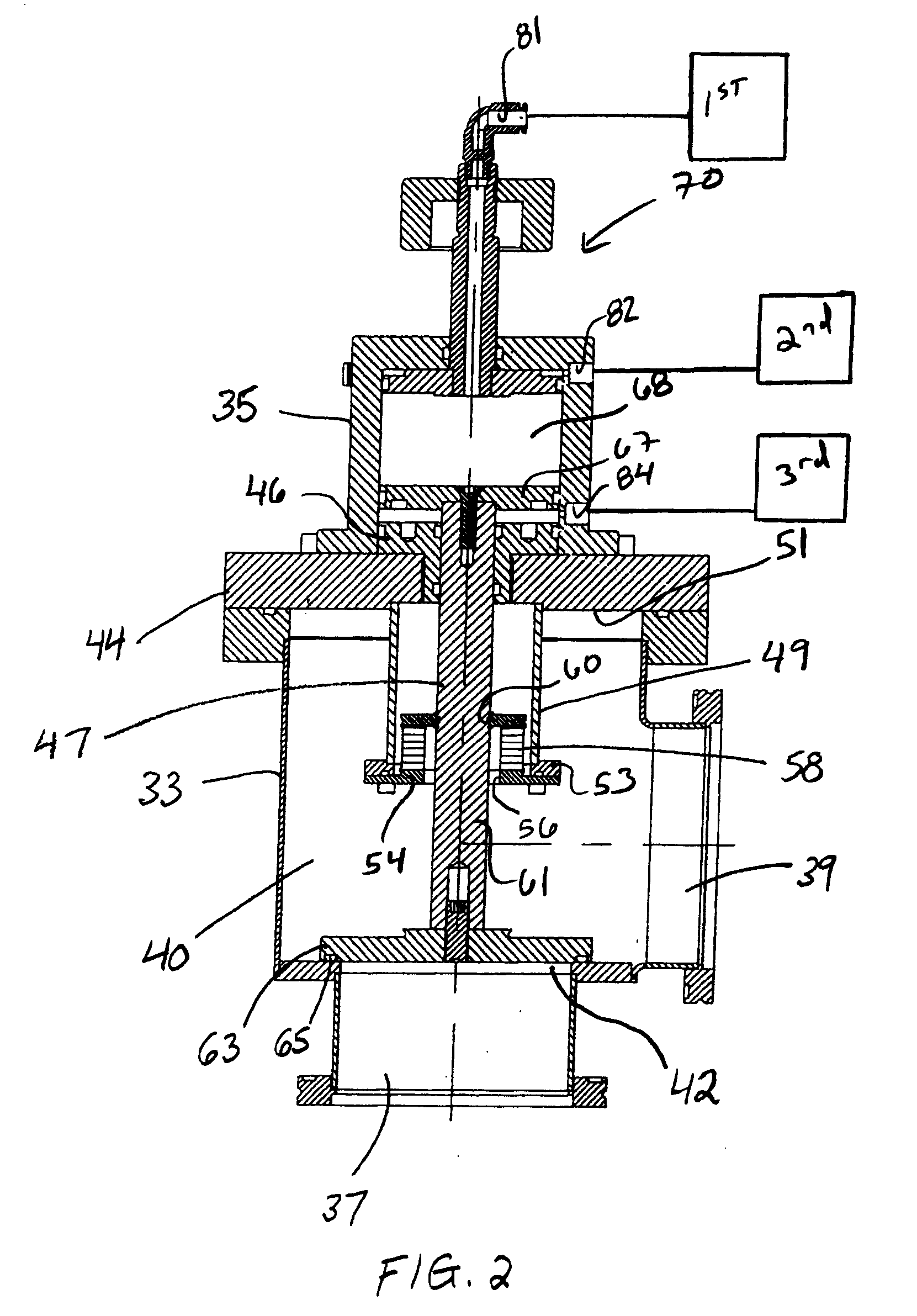
[0027] Turning now to the drawings, wherein like components are designated by like reference numerals throughout the various figures, attention is directed to FIG. 1 which shows an isometric view of an angle valve, generally designated 30.

[0028] Referring to FIG. 1, angle valve 30 includes a valve housing, generally designated 32. Housing 32 includes a main housing 33 and an upper housing 35. In the illustrated embodiment, a bottom wall of the main housing in...


PUM


Abstract

An angle valve including a valve housing defining a valve chamber and having a valve opening, a driveshaft reciprocally extending into the valve chamber through a driveshaft opening, a boss extending downwardly from a top wall of the valve chamber around the driveshaft, and a bellows having a lower end mounted to the boss and an upper end mounted to the driveshaft so as to isolate the driveshaft and the driveshaft opening from the valve chamber. A method of using the gate valve is also disclosed.

Description

CROSS-REFERENCE TO RELATED APPLICATIONS [0001] This application claims the benefit of under 35 U.S.C. §119(e) to U.S. Ser. No. 60 / 819,830, filed Jul. 10, 2006, incorporated herein by reference in its entirety.BACKGROUND OF THE INVENTION [0002] 1. Field of the Invention [0003] This invention relates, in general, to angle valves and more particularly to valves with adjustable opening positions and methods for their use. [0004] 2. Description of Related Art [0005] The angle valve of the present invention is directed to use with cluster platforms. In the semiconductor industry, substrate handling systems referred to as cluster assemblies move substrates into and out of process modules. Various processes are performed on the substrate unit in each process module. An example of such a cluster platform is the Marathon Series cluster platform manufactured and sold by Brooks Automation of Lowell, Mass. [0006] The sensitive nature of the fabrication materials and processes typically requires ...

Claims


Application Information

Patent Timeline
Patent Type & Authority Applications(United States)
IPC IPC(8): F16K1/00
CPCF16K31/1225
Inventor BRENES, ARTHUR J.
Owner HIGH VACUUM APP MFG
Why Eureka
Try Eureka