One-piece microcellular polyurethane insulator having different densities

a micro-cellular polyurethane and insulator technology, applied in the field of insulators for vehicles, can solve the problems of increasing the cost of manufacturing such insulators, and achieve the effect of increasing the block height, and reducing the cost of manufacturing insulators

Inactive Publication Date: 2008-01-17
BASF CORP
View PDF22 Cites 50 Cited by
  • Summary
  • Abstract
  • Description
  • Claims
  • Application Information

AI Technical Summary

Benefits of technology

[0009]Accordingly, the insulator has varying density such that the insulator has an increased block height without adversely affecting the load absorption and vibration dampening characteristics of the i

Problems solved by technology

The presence of multiple parts and the labor required to assemble th

Method used


Image

  • One-piece microcellular polyurethane insulator having different densities
  • One-piece microcellular polyurethane insulator having different densities
  • One-piece microcellular polyurethane insulator having different densities

Examples


first embodiment

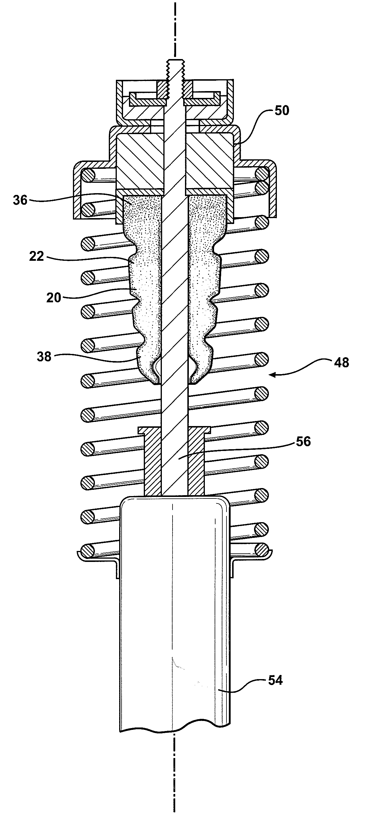
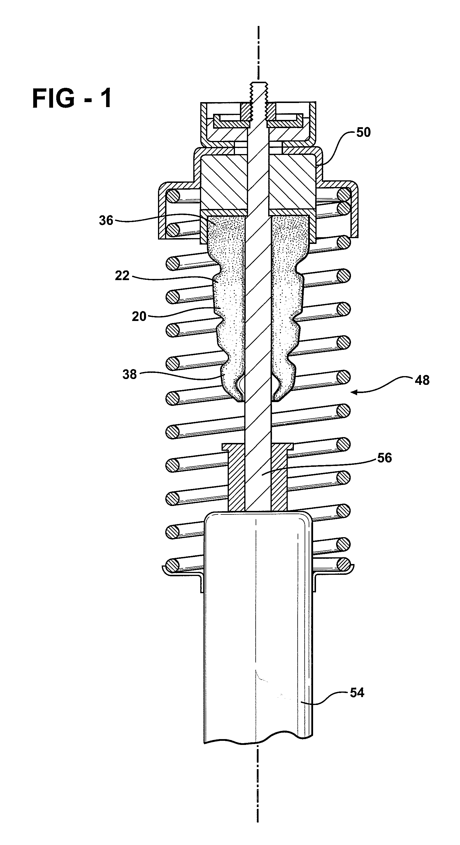
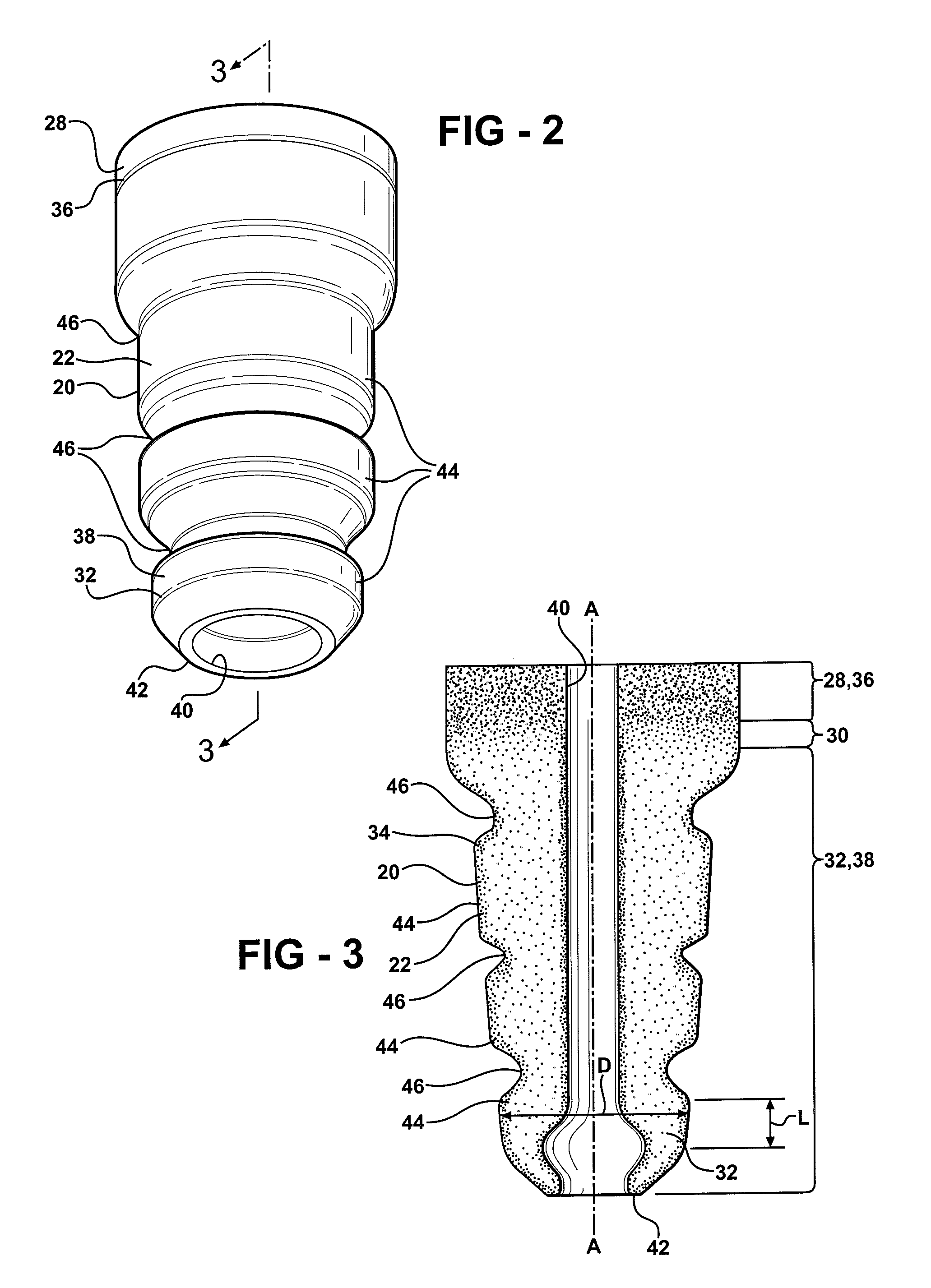
[0032]In the first embodiment, as shown in FIGS. 1-3, the first portion 28 is a shoulder portion 36 and the second portion 32 is a projection portion 38 such that the insulator 20 defines the jounce bumper 22. The intermediate portion 30 extends between the shoulder portion 36 and the projection portion 38. Specifically, the shoulder portion 36 extends along the axis A, the projection portion 38 extends along the axis A, and the intermediate portion 30 is disposed between the shoulder portion 36 and the projection portion 38 along the axis A.

[0033]The shoulder portion 36 defines the first density and the projection portion 38 defines the second density different from the first density. The intermediate portion 30 has a transitional density transitioning between the first density of the shoulder portion 36 and the second density of the projection portion 38.

[0034]Preferably, the first density of the shoulder portion 36 is greater than the second density of the projection portion 38 s...

second embodiment

[0046]In the second embodiment, as shown in FIGS. 5-7, the first portion 128 is a bottom portion 58 and the second portion 132 is a top portion 60 such that the insulator 120 defines the body insulator 24. The intermediate portion 130 extends between the bottom portion 58 and the top portion 60.

[0047]Specifically, the bottom portion 58 extends along the axis A, the top portion 60 extends along the axis A, and the intermediate portion 130 is disposed between the bottom portion 58 and the top portion 60 along the axis A,

[0048]The bottom portion 58 portion defines the first density and the top portion 60 defines the second density different from the first density. The intermediate portion 130 has the transitional density transitioning between the first density of the bottom portion 58 and the second density of the top portion 60.

[0049]Preferably, the first density of the bottom portion 58 is greater than the second density of the top portion 60 such that the compressibility of the top ...

third embodiment

[0056]In the third embodiment, the first portion 228 is a lip 76 and the second portion 232 is a rim 78 such that the insulator 220 defines the coil spring isolator 26. The intermediate portion 230 extends between the lip 76 and the rim 78.

[0057]Specifically, the lip 76 defines the first density and the rim 78 defines the second density. The intermediate portion 230 has the transitional density transitioning between the first density of the lip 76 and the second density of the rim 78.

[0058]Preferably, the first density of the lip 76 is greater than the second density of the rim 78 such that the compressibility of the rim 78 is greater than the compressibility of the lip 76. In other words, the rim 78 deforms more than the lip 76 when subject to a load.

[0059]More specifically, the lip 76, the intermediate portion 230, and the rim 78 are integrally formed of common homogenous MCU material for defining a one-piece coil spring isolator 26 having different densities. In other words, the ...


PUM


Abstract

An insulator for a vehicle includes a first portion extending along an axis, an intermediate portion extending from the first portion along the axis, and a second portion extending from the intermediate portion along the axis. The first portion defines a first density and the second portion defines a second density different from the first density. Preferably, the first density is greater than the second density such that the second portion is more compressible than the first portion. The first portion, the intermediate portion, and the second portion are integrally formed of a common homogeneous microcellular polyurethane material for defining a one-piece insulator having different densities. In exemplary embodiments, the insulator is further defined as a jounce bumper or a coil spring isolator for disposition in a wheel suspension system, and a body insulator for disposition in a mount assembly of a vehicle.

Description

BACKGROUND OF THE INVENTION[0001]1. Field of the Invention[0002]The present invention relates to an insulator for a vehicle which can be utilized as a jounce bumper or a coil spring isolator for disposition in a wheel suspension system, or a body insulator for disposition in a mount assembly of a vehicle.[0003]2. Description of the Related Art[0004]Insulators for absorbing loads and dampening vibrations in vehicles are known in the prior art. Such insulators include jounce bumpers and coil spring isolators for disposition in wheel suspension systems, and body insulators for disposition in mount assemblies. Insulators of these types are formed from elastomeric materials such as rubber or microcellular polyurethane (MCU). MCU provides several advantages over alternative materials. Specifically, MCU has a microcellular structure, i.e., the MCU presents cell walls defining cells, or void space. When not subject to compressive forces, the cell walls have an original shape and the cells a...

Claims


Application Information

Patent Timeline
IPC IPC(8): F16M1/00
CPCF16F1/3732F16F2224/005F16F9/58F16F3/093
Inventor DICKSON, DANIEL G.
Owner BASF CORP
Why Eureka
Try Eureka