Sanding Device for Rail Vehicles

a technology for rail vehicles and sanding devices, which is applied in the direction of locomotives, railway braking systems, piping arrangements, etc., can solve the problems of no optimal effect, no full effect of operating disturbances, etc., and achieve the effect of increasing the coefficient of adhesion between the wheels and the rails within a short time and improving the coefficient of adhesion

Inactive Publication Date: 2008-01-17
KNORR BREMSE SYST FUR SCHIENENFAHRZEUGE GMBH
View PDF4 Cites 1 Cited by
  • Summary
  • Abstract
  • Description
  • Claims
  • Application Information

AI Technical Summary

Benefits of technology

[0001]The present disclosure relates to a sanding device for vehicles, particularly for rail vehicles. In order to improve the coefficient of adhesion between the wheels and the running surface under unfavorable running surface conditions, vehicles are equipped with sanding systems. In the case of rail vehicles, sanding systems contribute to considerably increasing the coefficient of adhesion between the wheels and the rails within a short time.
[0004]The present disclosure relates to improving the adhesion between the wheels and the rail in the case of ice and wetness, without the occurrence of disturbances.
[0007]The present disclosure relates to providing a simpler and more economical method of apportioning the discharged quantity.
[0009]The present disclosure is based on an idea of providing the compressed air flowing into the sanding device, which is to be controlled in a continuous manner by switching the compressed-air supply on and off, and smoothed by way of a pressure container. It thereby becomes possible to make the discharge quantity dependent on the vehicle speed.
[0010]The present disclosure provides a sanding device which can discharge different quantities of sand as a function of the input pressure. The faster the rail vehicle travels, the more sand is discharged. According to the present disclosure, switching between two different sanding levels no longer takes place. Thus, according to the present disclosure, precisely the correct amount of sand no longer is present only at two speeds. Most importantly, when the travel is very slow, the discharged quantity of sand is no longer extremely high in comparison to the quantity of sand which would actually be needed. According to the present disclosure, the refilling of sand also becomes less frequent. It becomes possible to discharge the same quantity of sand per traveled meter. The present disclosure provides a system which is not susceptible to disturbances and operates continuously with compressed air.

Problems solved by technology

If an insufficient quantity of sand is discharged, the full effect of the improvement of the coefficient of adhesion is not achieved.
If, on the other hand, too much sand is discharged, there is also no optimal effect.
Switches are even occasionally clogged by too much sand, which results in operating disturbances.
A large amount of sand may severely interfere with the track facilities.
A clogging of track switches by sand may drastically impair the conductance between the wheels and the rails which is important for the signal transmission.
Such a deterioration of the conductance between the wheels and the rails has the risk that, in the event of improper care of the track facilities, the signal transmission may be impaired such that, in the worst case, a signal transmission does not take place or is faulty, so that accidents may occur.

Method used


Image

  • Sanding Device for Rail Vehicles
  • Sanding Device for Rail Vehicles

Examples


Embodiment Construction

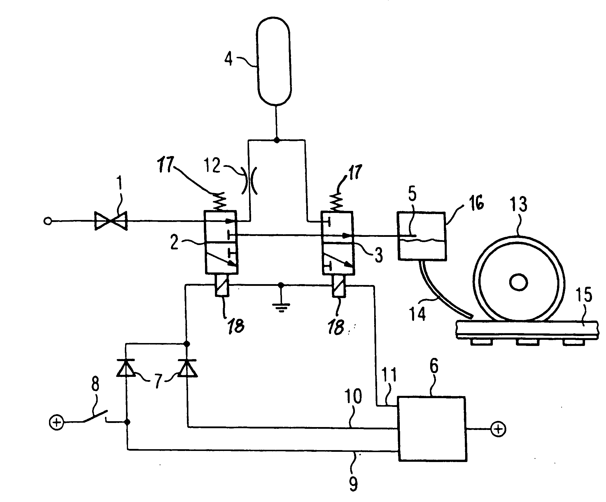
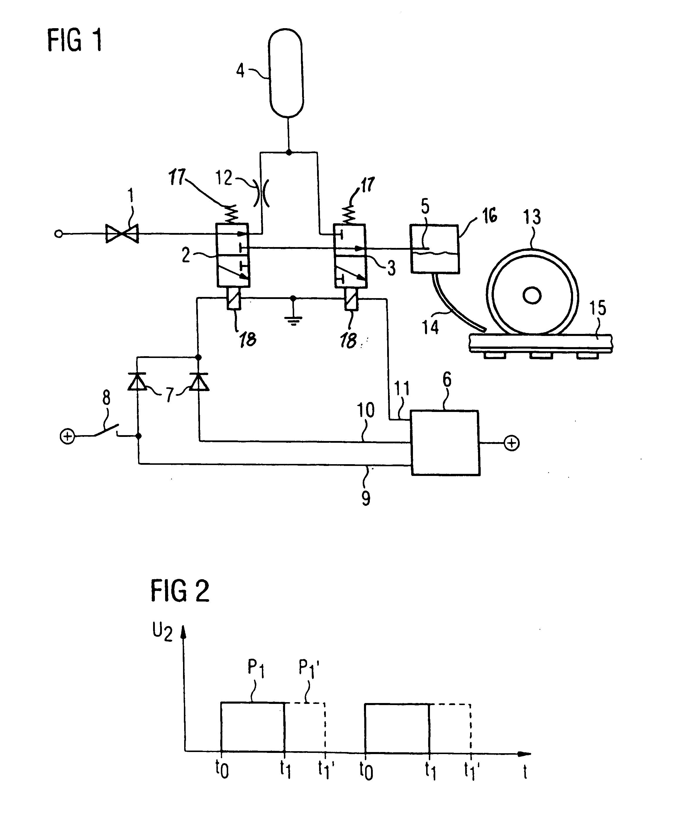
[0014]A sanding device according to the present disclosure includes a pressure reducing valve 1 to which the pressure from a pneumatic braking system of a rail vehicle is applied. Also included is a first pneumatic valve 2 in the form, for example, of a 3 / 2-way valve, a second pneumatic valve 3 in the form, for example, of a 3 / 2-way valve, a pressure container 4, a sanding nozzle 5 which is arranged in a sanding container 16, and a brake control device 6.

[0015]The output of the pressure reducing valve I is shown, for example, in FIG. 1, connected with an input of the first 3 / 2-way valve 2. One of two outputs of the first 3 / 2-way valve 2 is connected by way of a throttle 12 with a connection of the pressure container 4. This connection of the pressure container 4 is connected with one of two inputs of the second 3 / 2-way valve 3. The other of the two outputs of the first 3 / 2-way valve 2 is shown connected with the other of the two inputs of the second 3 / 2-way valve 3. An output of the...


PUM


Abstract

The present disclosure relates to a sanding device for a vehicle. The sanding device includes a compressed-air connection, at least one pneumatic valve, a pressure container and a sanding nozzle arranged in a sand container.

Description

BACKGROUND AND SUMMARY[0001]The present disclosure relates to a sanding device for vehicles, particularly for rail vehicles. In order to improve the coefficient of adhesion between the wheels and the running surface under unfavorable running surface conditions, vehicles are equipped with sanding systems. In the case of rail vehicles, sanding systems contribute to considerably increasing the coefficient of adhesion between the wheels and the rails within a short time.[0002]In the case of rail vehicles, the sand is discharged in front of the wheels, so that the rail vehicles roll by way of a “sanded” rail with a considerably increased coefficient of adhesion. The effect of the sanding is a function of the quantity of the discharged sand per covered running path. Ideally, a constant quantity of sand should be discharged per meter of running path. If an insufficient quantity of sand is discharged, the full effect of the improvement of the coefficient of adhesion is not achieved. If, on ...

Claims


Application Information

Patent Timeline
Patent Type & Authority Applications(United States)
IPC IPC(8): B60B39/00B60B39/08B60T17/04B61H11/00
CPCB60B39/086B60B39/023
Inventor KNOSS, RAINER
Owner KNORR BREMSE SYST FUR SCHIENENFAHRZEUGE GMBH
Why Eureka
Try Eureka