Magnetic pistons engine

a technology of magneto-cranked pistons and pistons, which is applied in the direction of mechanical energy handling, electrical apparatus, dynamo-electric machines, etc., to achieve the effect of increasing fuel costs and diminishing natural fuel reserves

Inactive Publication Date: 2008-01-17
TOGARE RADHAKRISHNA SHESHA IYENGAR
View PDF23 Cites 38 Cited by
  • Summary
  • Abstract
  • Description
  • Claims
  • Application Information

AI Technical Summary

Benefits of technology

[0006] Unlike Steam engines and Internal Combustion engines, Maps engine is environmentally very safe since it does not burn any fuel. Due to th...

Problems solved by technology

Further, due to the principle of its operation, Maps engine uses ...

Method used


Image

  • Magnetic pistons engine
  • Magnetic pistons engine
  • Magnetic pistons engine

Examples


Embodiment Construction

[0070] Before we turn our attention to the detailed operation of environmental friendly, highly efficient Maps engine, let us understand the basic principle of magnetism on which Maps engine has been invented. A little knowledge on magnetism and magnetic materials is desirable but not necessary to understand the concept of this invention.

[0071] 5.1 Principle of Magnetism

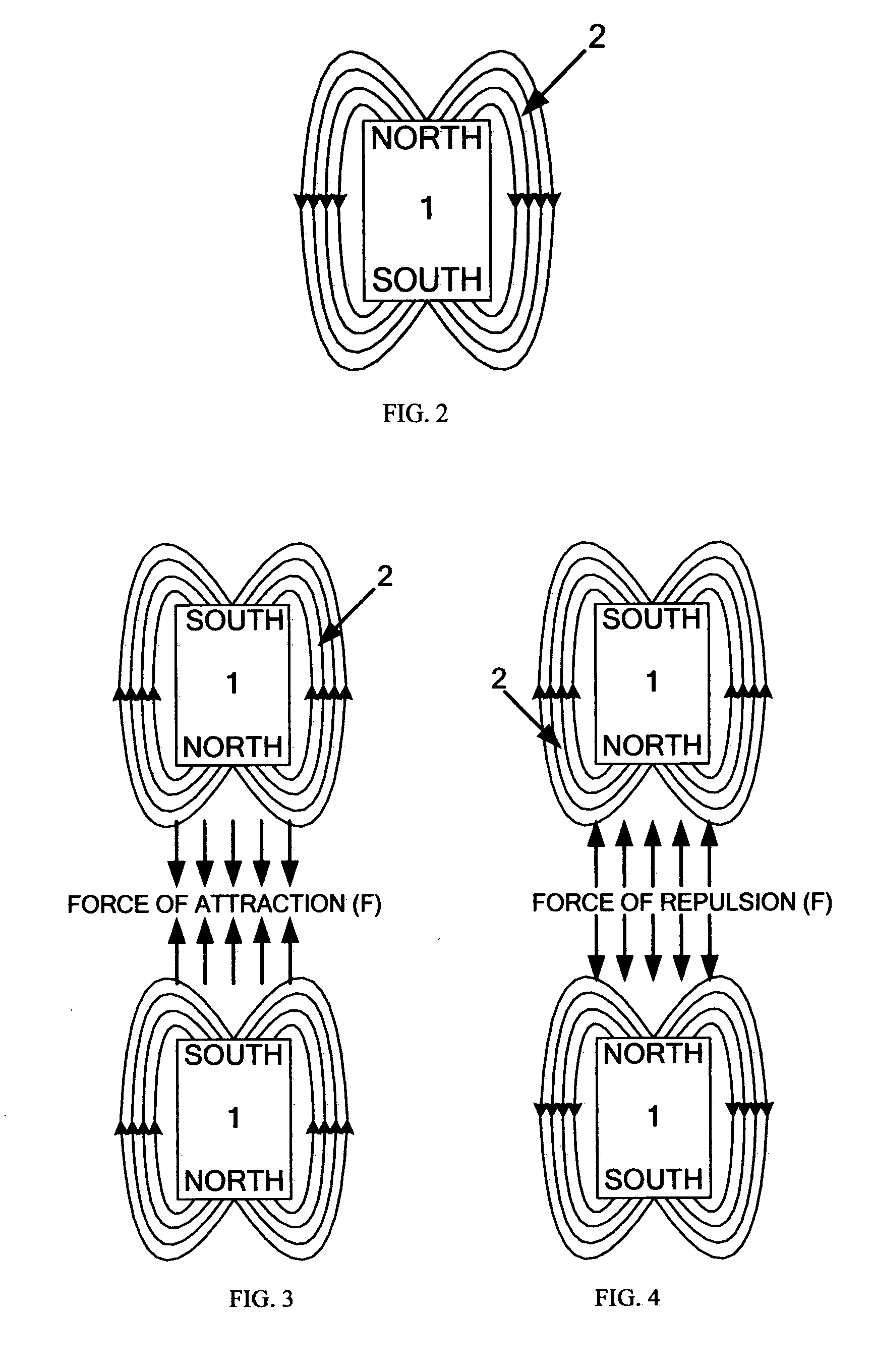
[0072]FIG. 2 shows a permanent magnet 1. A permanent magnet 1, also called magnet 1, is a piece of material that has equal number of poles. A pole can be described as the point where all the lines 2 of magnetic force meet. A magnet 1 will have at-least two poles, one is North and the other is South. The lines 2 of the magnetic field, also called the flux lines 2, turn around the magnet 1 in all directions, leaving out from the North pole and entering in from the South pole.

[0073] Note that the flux lines 2 in FIG. 2 are imaginary lines 2 shown only for the purpose of explanation. The extension of the flux lines 2 ...


PUM


Abstract

The present invention relates to the “Magnetic pistons engine”, hereafter called “Maps engine” or “RAT engine” or “engine” that works on the principle of magnetism. It can be used to perform various tasks and functions that involve application of force or displacement of objects. This method provides an environmental friendly, very high efficiency engine that can complement or replace any engines that use fossil fuel, bio-fuel, solar power, wind power, hydro power, electricity, stored energy, or other energy sources.

Description

CROSS-REFERENCE TO RELATED APPLICATION [0001] This application claims the benefit of U.S. provisional patent application Ser. No. 60 / 813,259 filed Jun. 12, 2006.FIELD OF THE INVENTION [0002] The present invention relates to the “Magnetic pistons engine”, hereafter called “Maps engine” or “RAT engine” or “engine” that works on the principle of magnetism. It can be used to perform various tasks and functions that involve application of force or displacement of objects. This method provides an environmental friendly, very high efficiency engine that can complement or replace any engines that use fossil fuel, bio-fuel, solar power, wind power, hydro power, electricity, stored energy, or other energy sources. BACKGROUND OF THE INVENTION [0003] Generating linear or circular motion power using different technologies is known for centuries. There are many types of engines to accomplish this. Internal Combustion engines and Steam engines are few examples of linear reciprocating engines. Whil...

Claims


Application Information

Patent Timeline
IPC IPC(8): H02K35/00
CPCH02K53/00H02K7/075
Inventor TOGARE, RADHAKRISHNA SHESHA IYENGAR
Owner TOGARE RADHAKRISHNA SHESHA IYENGAR
Why Eureka
Try Eureka