Fuel injection equipment, internal combustion engine, and control method of fuel injection equipment

a fuel injection equipment and internal combustion engine technology, applied in the direction of low pressure fuel injection, mechanical equipment, machines/engines, etc., can solve the problems of limiting the improvement of fuel cost, the air-fuel mixture cannot reach the sparking plug, and the inability to perform stable combustion, so as to improve the efficiency of combustion and improve the fuel cost. , the effect of stable combustion

Inactive Publication Date: 2006-04-04
HITACHI LTD
View PDF8 Cites 8 Cited by
  • Summary
  • Abstract
  • Description
  • Claims
  • Application Information

AI Technical Summary

Benefits of technology

[0007]Because it is possible to make fuel spray reach the plug even when the airflow is weak, the stable combustion is obtained. As a result, the combustion efficiency can be improved, and thus the fuel cost can be improved.

Problems solved by technology

Further, the air-fuel mixture cannot reach the sparking plug because the pressure in the combustion chamber is high when the air-fuel ratio is made a lean state to improve the fuel cost, and the stable combustion cannot be performed.
In a word, there is a limit in the improvement of the fuel cost.

Method used


Image

  • Fuel injection equipment, internal combustion engine, and control method of fuel injection equipment
  • Fuel injection equipment, internal combustion engine, and control method of fuel injection equipment
  • Fuel injection equipment, internal combustion engine, and control method of fuel injection equipment

Examples


Embodiment Construction

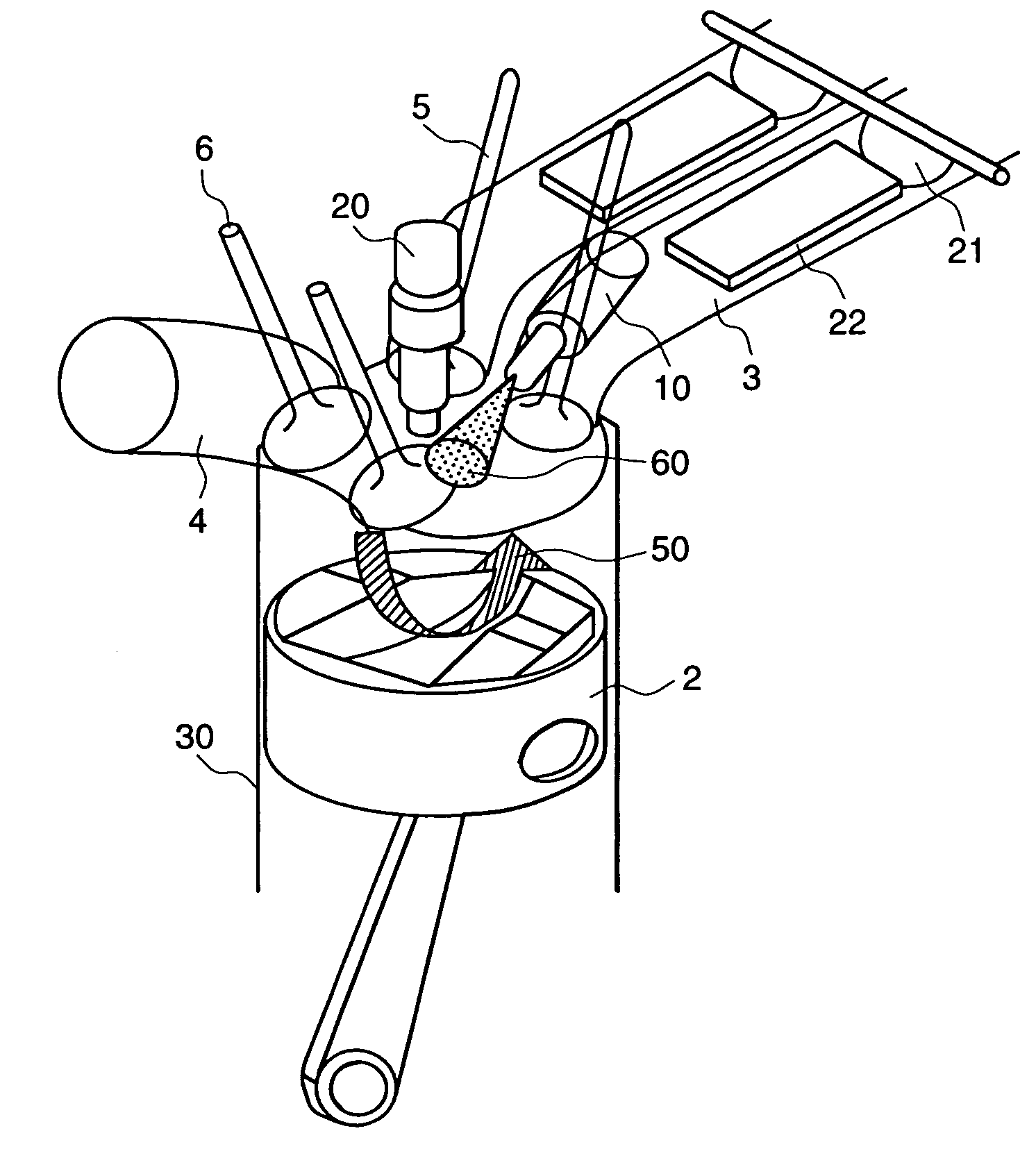
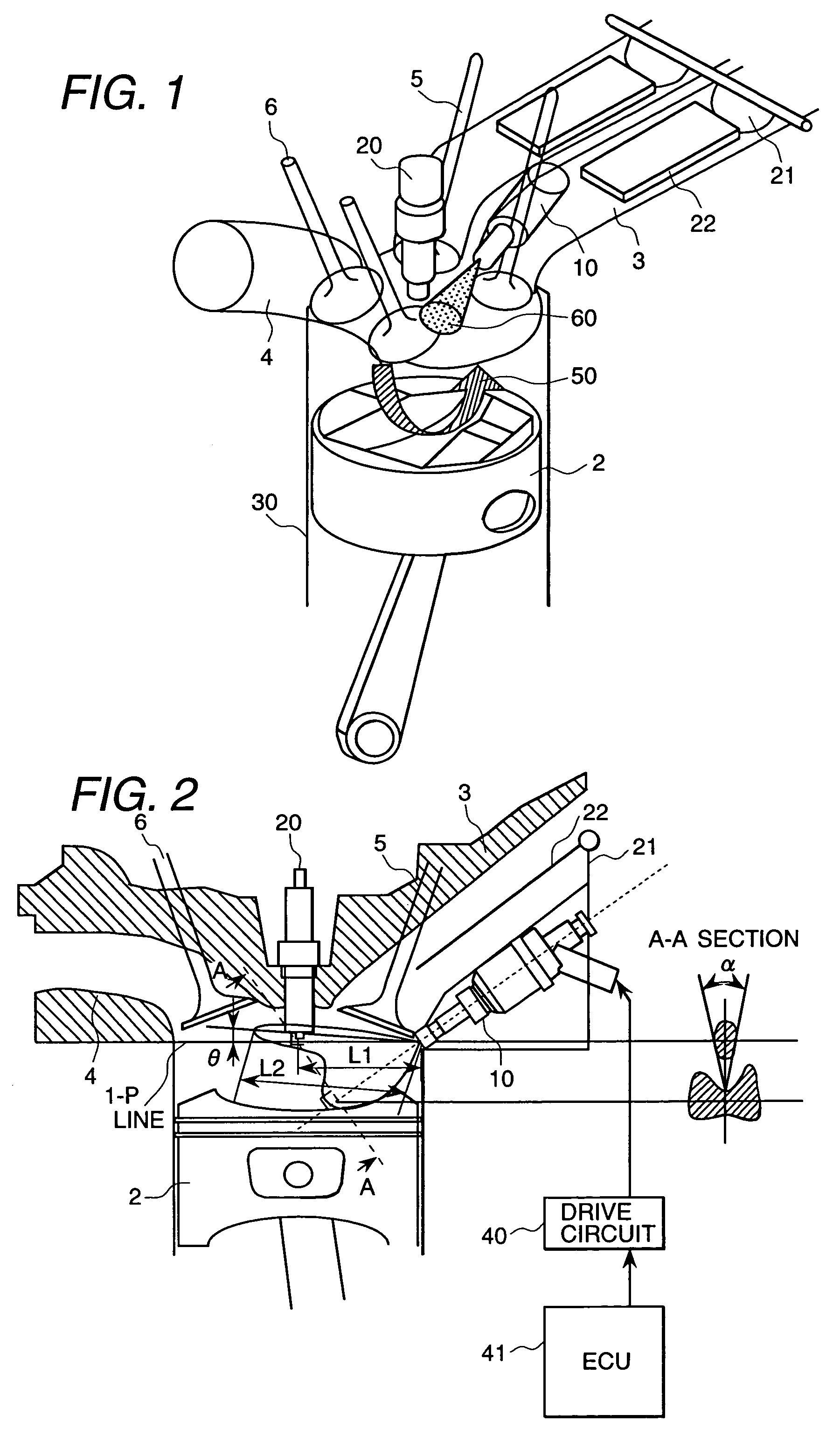
[0032]In the cylinder injection engine, the fuel injection valve is provided at angle of 20° to 50° with the horizontal plane of the combustion chamber and between two intake ports of the combustion chamber. The airflow formed by the flow generation means such as the swirl control valves which are provided in the intake port is mixed with the fuel injected aiming at the cavity provided to the piston when the stratification burns. The air-fuel mixture is led to the sparking plug arranged in the center part of the combustion chamber, and ignited. It is necessary to provide for a necessary fuel spray requirement when the air-fuel ratio is made a lean state to improve the fuel cost and perform the stratification combustion in the cylinder injection type and spark ignition internal combustion engine. However, there is a problem that fuel spray do not reach the sparking plug because of the increase in atmosphere pressure of the combustion chamber, and the stratification combustion in the ...


PUM


Abstract

A fuel injection equipment to control the instability of combustion when the airflow is weak, and improve the fuel cost. A fuel injection equipment for an cylinder injection type and spark ignition type internal combustion engine that injects gasoline directly to a combustion chamber, wherein the top angle at the point of fuel spray in the pressurized atmosphere of absolute pressure 0.5 MPa is from −10° to 10°. Further, the fuel is injected at the compression stroke of the internal combustion engine which installs the fuel injection equipment, and said internal combustion engine is started.

Description

BACKGROUND OF THE INVENTION[0001]The present invention relates to a method of controlling the fuel injection equipment, an internal combustion engine and a fuel injection equipment.[0002]In the Japanese Patent Application No. 2001-214744, it has been described that an excellent, homogeneous air-fuel mixture can be formed even when a large amount of fuel is necessary in the homogeneous combustion, in the fuel injection equipment for an cylinder injection type and spark ignition type internal combustion engine which can execute the stratification combustion of the fuel injection at the compression stroke and the homogeneous combustion of the fuel injection at the intake stroke.[0003]In the prior art, the best fuel spray form of the air guide type cylinder injection is not referred. Further, the air-fuel mixture cannot reach the sparking plug because the pressure in the combustion chamber is high when the air-fuel ratio is made a lean state to improve the fuel cost, and the stable comb...

Claims


Application Information

Patent Timeline
Patent Type & Authority Patents(United States)
IPC IPC(8): F02B17/00F02B23/10F02B75/12F02P13/00F02F3/26F02M51/08F02M61/14F02M61/18
CPCF02B17/005F02B23/104F02M61/162F02M61/1806F02B2023/103F02B2023/106F02B2075/125Y02T10/123F02M69/045Y02T10/125F02F3/26Y02T10/12
Inventor NAKAYAMA, YOKOSUKEGAWA, YOSHIHIRONOGI, TOSHIHARU
Owner HITACHI LTD
Why Eureka
Try Eureka