Control method of external control type fan clutch

a control method and fan clutch technology, applied in the direction of fluid couplings, positive displacement liquid engines, couplings, etc., can solve the problems of affecting the temperature of the engine cooling liquid cannot influence the cooling performance of the engine, and the fuel cost becomes worse, so as to achieve the cooling performance of the air conditioner, the preferable cooling efficiency of the capacitor of the air conditioner can be maintained, and the effect of reducing the noise of the fan

Active Publication Date: 2012-02-21
USUI KOKUSAI SANGYO KAISHA LTD
View PDF24 Cites 6 Cited by
  • Summary
  • Abstract
  • Description
  • Claims
  • Application Information

AI Technical Summary

Benefits of technology

[0012]In accordance with the control method of the present invention, the fan rotation can be controlled so as to always lie in a preferable temperature range of engine combustion efficiency by controlling the temperature of the cooling liquid of the radiator as a direct control parameter. Further, the fan rotation preferable in cooling efficiency of the capacitor of the air conditioner can be maintained and cooling performance of the air conditioner can be improved by always detecting the on-off situation of the air conditioner and the compressor pressure. Further, the associative rotation of the fan due to starting acceleration and outrunning acceleration from an idle time can be prevented and fan noises can be reduced by detecting the engine rotating speed and an accelerator aperture. Further, the upper limit rotating speed is set to the optimum fan rotating speed required from the engine side. The fan rotating speed control signal is temporarily stopped (cut) on the basis of the differential speeds between the engine rotating speed, the fan rotating speed and the optimum fan rotating speed. The fan rotating speed control signal is temporarily stopped (cut) on the basis of the engine rotating acceleration or the accelerator (throttle) position acceleration. The limit is given to the changing rate of the optimum fan rotating speed on the basis of the changing rate of the optimum fan rotating speed. The following many excellent effects can be obtained by taking such means, etc. Namely, the response delay with respect to control instructions of the fan rotation is reduced, and the associative rotation is reduced at the engine rotation changing time, the engine starting time, etc., and the fan rotating behavior can be stabilized. Further, fan consumption horsepower is reduced (fuel cost is improved) and fan noises are reduced, etc.

Problems solved by technology

However, no temperature of an engine cooling liquid having an influence on engine cooling performance can be set to a direct control object in the latter control method (JP-A-9-119455) of the viscous fluid joint of the system for changing the oil supply amount by opening and closing the valve by deforming the bimetal reacting on the temperature of the passing wind of the radiator, and changing the fan rotation.
Therefore, this control method has disadvantages in that a horsepower loss is caused by the unnecessary fan rotation, and fuel cost becomes worse, and no preferable fan rotation for cooling a capacitor of an air conditioner (A / C) can be maintained and no fan noises due to associative rotation of the unnecessary fan rotation at an accelerating time can be restrained, etc.
Further, in the conventional control method of the external control type fan clutch, when the clutch is once turned on and is rotated by setting a control area of the fan rotating speed from an OFF rotating area to an entire ON rotating area, responsibility to control support just after this rotation of the clutch is bad and the associative rotation is generated.
Further, since only the fan rotating speed is set to a judging material of the control, this control method has disadvantages in that the associative rotation is generated at a sudden changing time of the engine rotating speed, and a fan rotating behavior becomes unstable, etc.

Method used


Image

  • Control method of external control type fan clutch
  • Control method of external control type fan clutch
  • Control method of external control type fan clutch

Examples


Embodiment Construction

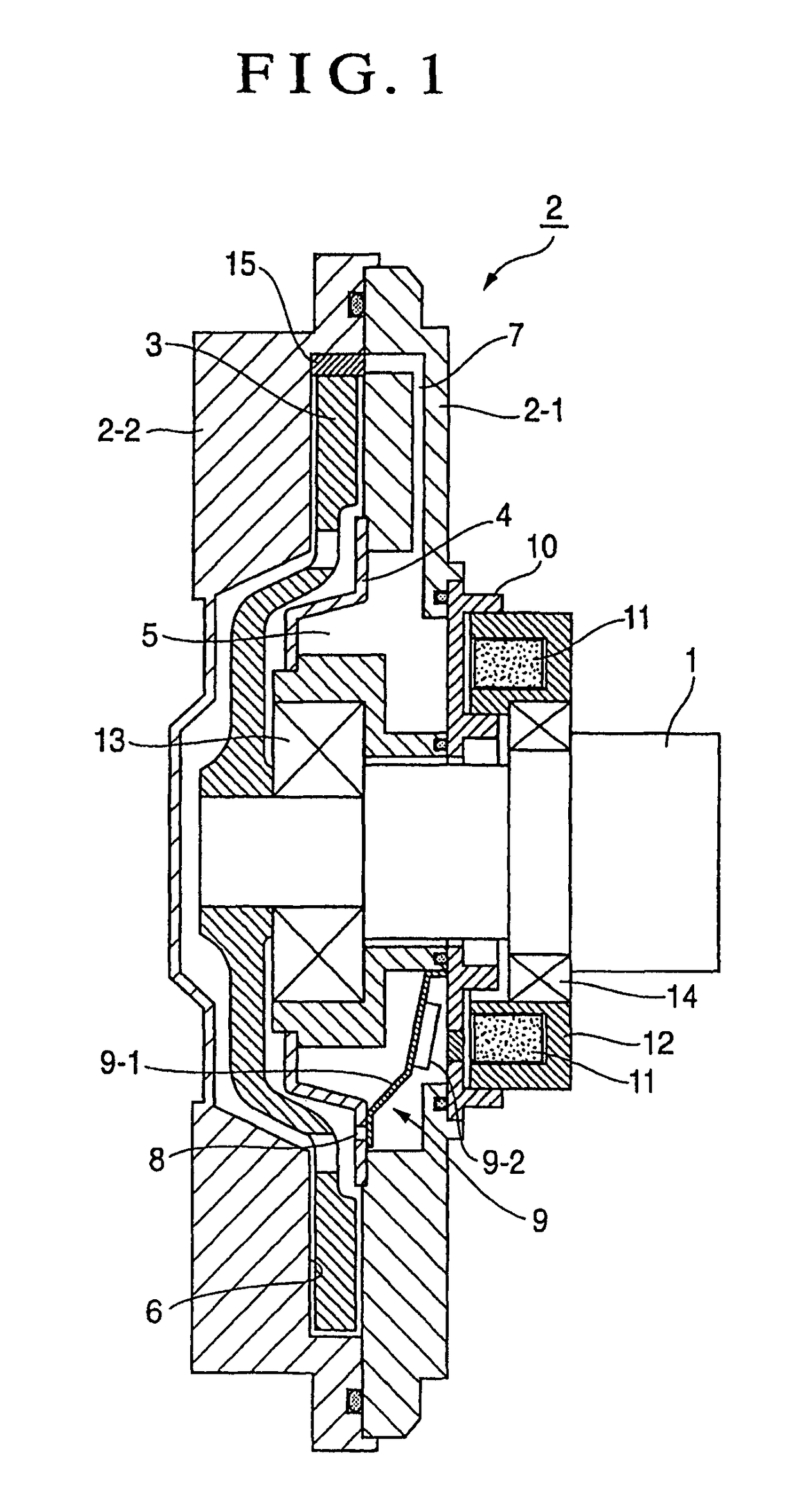
[0027]In the present invention, the external control type fan clutch device shown in FIG. 1, a sealing housing 2 constructed by a case 2-1 and a cover 2-2 is supported by a rotating shaft body (drive shaft) 1 rotated by driving a driving section (engine) through a bearing 13. The interior of this sealing housing 2 is partitioned into an oil reservoir chamber 5 and a torque transmission chamber 6 by a partition plate 4 with an oil supply adjusting hole 8. A drive disk 3 fixedly attached to the tip of the rotating shaft body 1 is stored into the torque transmission chamber 6 so as to form a torque transmitting clearance between the drive disk 3 and the inner circumferential face of the torque transmission chamber.

[0028]A dam 15 is arranged in one portion of the inner circumferential wall face of the cover 2-2 opposed to the outer circumferential wall portion of the drive disk 3 for collecting and reservoiring oil at the rotating time.

[0029]A valve member 9 for oil supply for opening a...


PUM


Abstract

The invention provides a control method of an external control type fan clutch able to improve engine performance, fuel cost and cooling performance of a capacitor of an air conditioner (A/C) and restrain fan noises due to associative rotation. Namely, in the external control type fan clutch device constructed so as to control the opening and closing of a supply adjusting hole of oil by a valve member operated by an electromagnet, the opening and closing of the supply adjusting hole of the oil is on-off-controlled with the temperature of a cooling liquid of a radiator, a fan rotating speed, the temperature of transmission oil, a vehicle speed, an engine rotating speed, the pressure of a compressor of the air conditioner, etc. as parameters.

Description

TECHNICAL FIELD[0001]The present invention generally relates to a control method of an external control type fan clutch of a system in which fan rotation for cooling an engine in an automobile, etc., is controlled in accordance with a temperature change of the external circumference and changes of conditions of driving.BACKGROUND ART[0002]As a fan-coupling device of this kind, the interior of a sealing housing constructed by a case and a cover is partitioned into an oil reservoir chamber and a torque transmission chamber for internally mounting a drive disk by a partition plate having a supply adjusting hole of oil. A dam is formed in one portion of the inner circumferential wall face of the sealing housing side opposed to the outer circumferential wall portion of the drive disk for collecting and reservoiring the oil at the rotating time. A circulating flow passage is formed between oil reservoir chambers by the torque transmission chamber so as to be connected to the dam. The fan-...

Claims


Application Information

Patent Timeline
Patent Type & Authority Patents(United States)
IPC IPC(8): F16D31/00F01P7/04F01P7/08F01P7/14F04D25/02F16D35/02
CPCF01P7/042F04D25/022F16D35/024F01P2025/04F01P2025/40F01P2025/52F01P2025/64F01P2025/66F01P7/14
Inventor SHIOZAKI, KENIIDA, YOSHINOBU
Owner USUI KOKUSAI SANGYO KAISHA LTD
Why Eureka
Try Eureka