Downhole Coils

a coil and coil technology, applied in the direction of contact member penetrating/cutting insulation/cable strands, coupling device connections, borehole/well accessories, etc., can solve the problems of inherently finite life of batteries, limiting the options for generating and providing power to downhole components, and increasing the number and complexity of downhole drilling systems

Inactive Publication Date: 2008-01-17
SCHLUMBERGER TECH CORP
View PDF103 Cites 291 Cited by
  • Summary
  • Abstract
  • Description
  • Claims
  • Application Information

AI Technical Summary

Benefits of technology

[0012] In one aspect of the invention, a downhole tool string component comprises a tubular body with at least one end adapted for threaded connection to an adjacent tool string component. The end comprises at least one shoulder adapted to abut an adjacent shoulder of an adjacent end of the adjacent tool string component. An annular magnetic coupler is disposed within an annular recess formed in the at least one shoulder, and the magnetic coupler comprises a coil in electrical communication with an electrical conductor that is in electrical communication with an electronic device secured to the tubular body. The coil comprises a plurality of windings of wire strands that are electrically isolated from one another and which are disposed in an annular trough of magnetic material secured within the annular recess.

Problems solved by technology

Downhole sensors, tools, telemetry components and other electronic components continue to increase in both number and complexity in downhole drilling systems.
Constraints imposed by downhole tools and the harsh downhole environment significantly limit options for generating and providing power to downhole components.
Batteries, however, may be hindered by their inherently finite life and the need for frequent replacement and / or recharging.
This may be especially problematic in downhole drilling applications where access to batteries requires tripping and disassembly of the tool string.
Battery function may also be impaired by extreme temperatures, pressures, or other conditions found downhole.
Many types of batteries may be unable to reliably operate in downhole conditions.
Furthermore, batteries may be required everywhere electronic equipment is located downhole, requiring large numbers of batteries and significant time for installation and replacement.
This approach, however, may also have its problems and limitations.
Because a tool string may extend 20,000 feet or more into the ground, power transmitted along transmission lines may attenuate to an unacceptable level before it reaches its destination.

Method used


Image

  • Downhole Coils
  • Downhole Coils
  • Downhole Coils

Examples


Embodiment Construction

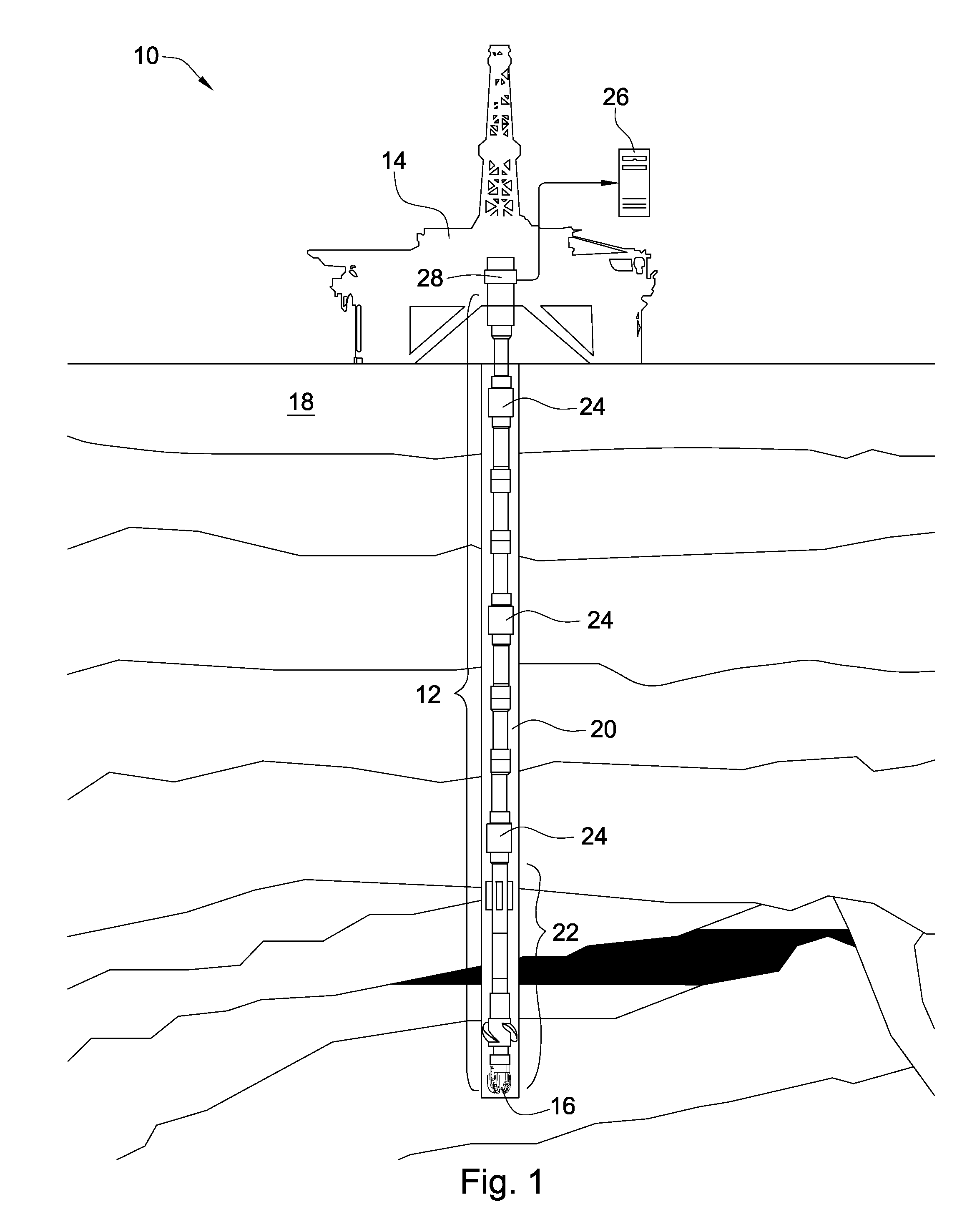
[0034] Referring to FIG. 1, one embodiment of a downhole drilling system 10 for use with the present invention includes a tool string 12 having multiple sections of drill pipe and other downhole tools. The tool string 12 is typically rotated by a drill rig 14 to turn a drill bit 16 that is loaded against a formation 18 to form a borehole 20. Rotation of the drill bit 16 may alternatively be provided by other downhole tools such as drill motors or drill turbines located adjacent to the drill bit 16.

[0035] The tool string 12 includes a bottom-hole assembly 22 which may include the drill bit 16 as well as sensors and other downhole tools such as logging-while-drilling (“LWD”) tools, measurement-while-drilling (“MWD”) tools, diagnostic-while-drilling (“DWD”) tools, or the like. The bottom-hole assembly 22 may also include other downhole tools such as heavyweight drill pipe, drill collar, crossovers, mud motors, directional drilling equipment, stabilizers, hole openers, sub-assemblies, ...


PUM


Abstract

In one aspect of the invention, a downhole tool string component comprises a tubular body with at least one end adapted for threaded connection to an adjacent tool string component. The end comprises at least one shoulder adapted to abut an adjacent shoulder of an adjacent end of the adjacent tool string component. An annular magnetic coupler is disposed within an annular recess formed in the at least one shoulder, and the magnetic coupler comprises a coil in electrical communication with an electrical conductor that is in electrical communication with an electronic device secured to the tubular body. The coil comprises a plurality of windings of wire strands that are electrically isolated from one another and which are disposed in an annular trough of magnetic material secured within the annular recess.

Description

CROSS REFERENCE TO RELATED APPLICATIONS [0001] This application is a continuation-in-part of U.S. application Ser. No. 11 / 739,344 filed on Apr. 24, 2007 and entitled “System and Method for Providing Electrical Power Downhole.” U.S. application Ser. No. 11 / 739,344 is a continuation in-part of U.S. application Ser. No. 11 / 421,387 filed on May 31, 2006 and entitled, “Wired Tool String Component.” U.S. application Ser. No. 11 / 421,387 is a continuation-in-part of U.S. application Ser. No. 11 / 421,357 filed on May 31, 2006 and entitled, “Wired Tool String Component.” U.S. application Ser. No. 11 / 421,357 is a continuation in-part of U.S. application Ser. No. 11 / 133,905 filed on May 21, 2005 and entitled, “Downhole Component with Multiple Transmission Elements.” All of these applications are herein incorporated by reference for all that they contain.BACKGROUND OF THE INVENTION [0002] The present invention relates to downhole drilling, and more particularly, to systems and methods for transmi...

Claims


Application Information

Patent Timeline
Patent Type & Authority Applications(United States)
IPC IPC(8): H01R4/24F16L55/00H01R11/00
CPCE21B17/003E21B17/028E21B41/0085H01F38/14F16L15/08F16L25/01F16L25/021F16L15/006
Inventor HALLBOSWELL, CRAIG
Owner SCHLUMBERGER TECH CORP
Why Eureka
Try Eureka