Feedthrough multilayer capacitor

a multi-layer capacitor and capacitor technology, applied in the direction of feed-through capacitors, fixed capacitor details, fixed capacitors, etc., can solve the problems of contradictory demands for greater capacity and greater equivalent series resistance in feed-through multi-layer capacitors, and no consideration has been made for increasing equivalent series, so as to achieve the effect of increasing equivalent series resistan

Active Publication Date: 2008-01-17
TDK CORPARATION
View PDF2 Cites 5 Cited by
  • Summary
  • Abstract
  • Description
  • Claims
  • Application Information

AI Technical Summary

Benefits of technology

[0014]The present invention can provide a feedthrough multilaye

Problems solved by technology

However, no consideration has been made for increasing the equivalent series resistance in the feedthrough multilayer capacitor described in Japanese Patent Applica

Method used


Image

  • Feedthrough multilayer capacitor
  • Feedthrough multilayer capacitor
  • Feedthrough multilayer capacitor

Examples


first embodiment

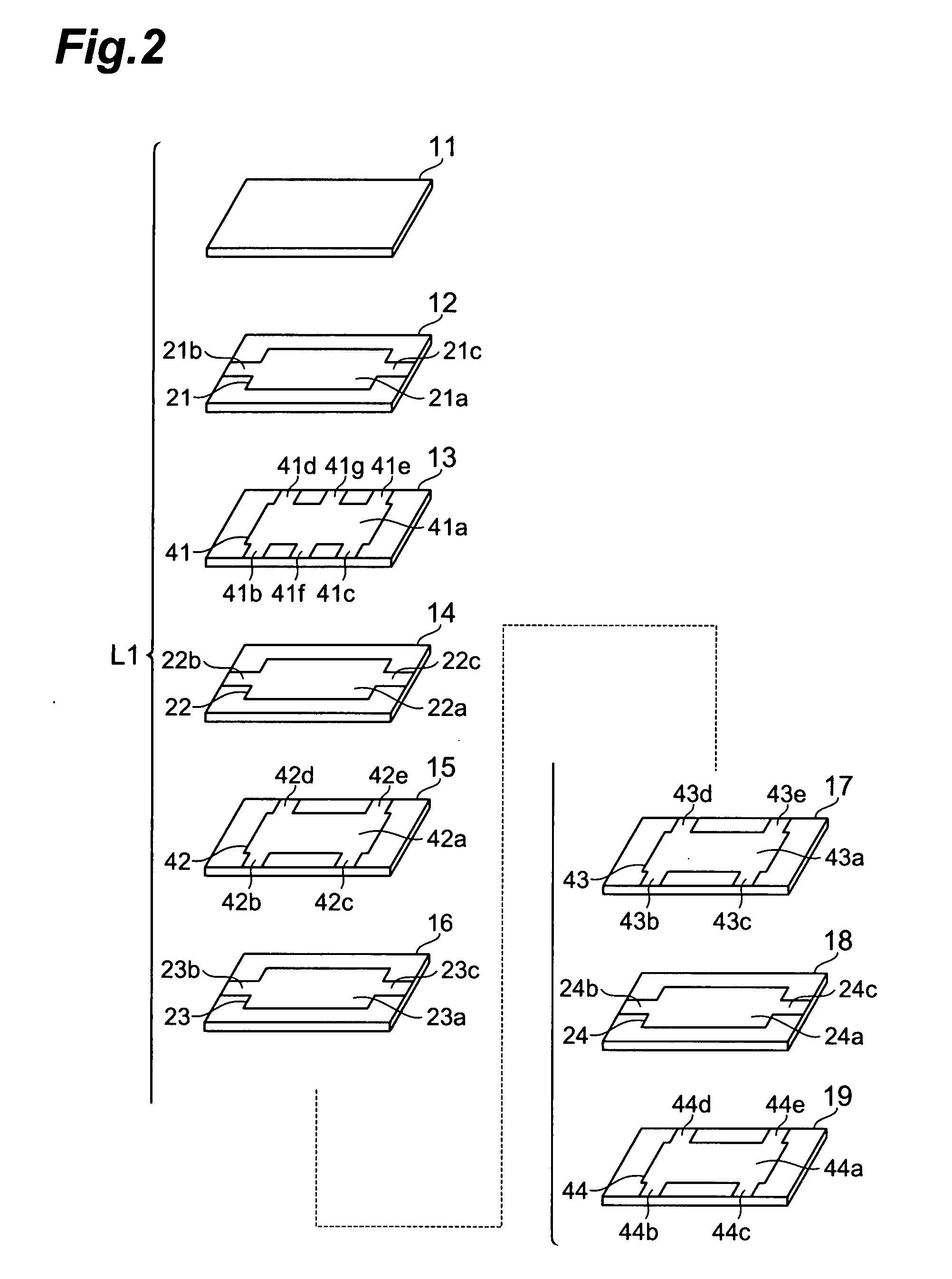
[0025]With reference to FIGS. 1 and 2, the structure of feedthrough multilayer capacitor C1 in accordance with a first embodiment will be explained. FIG. 1 is a perspective view of the feedthrough multilayer capacitor in accordance with the first embodiment. FIG. 2 is an exploded perspective view of the capacitor body included in the feedthrough multilayer capacitor in accordance with the first embodiment.

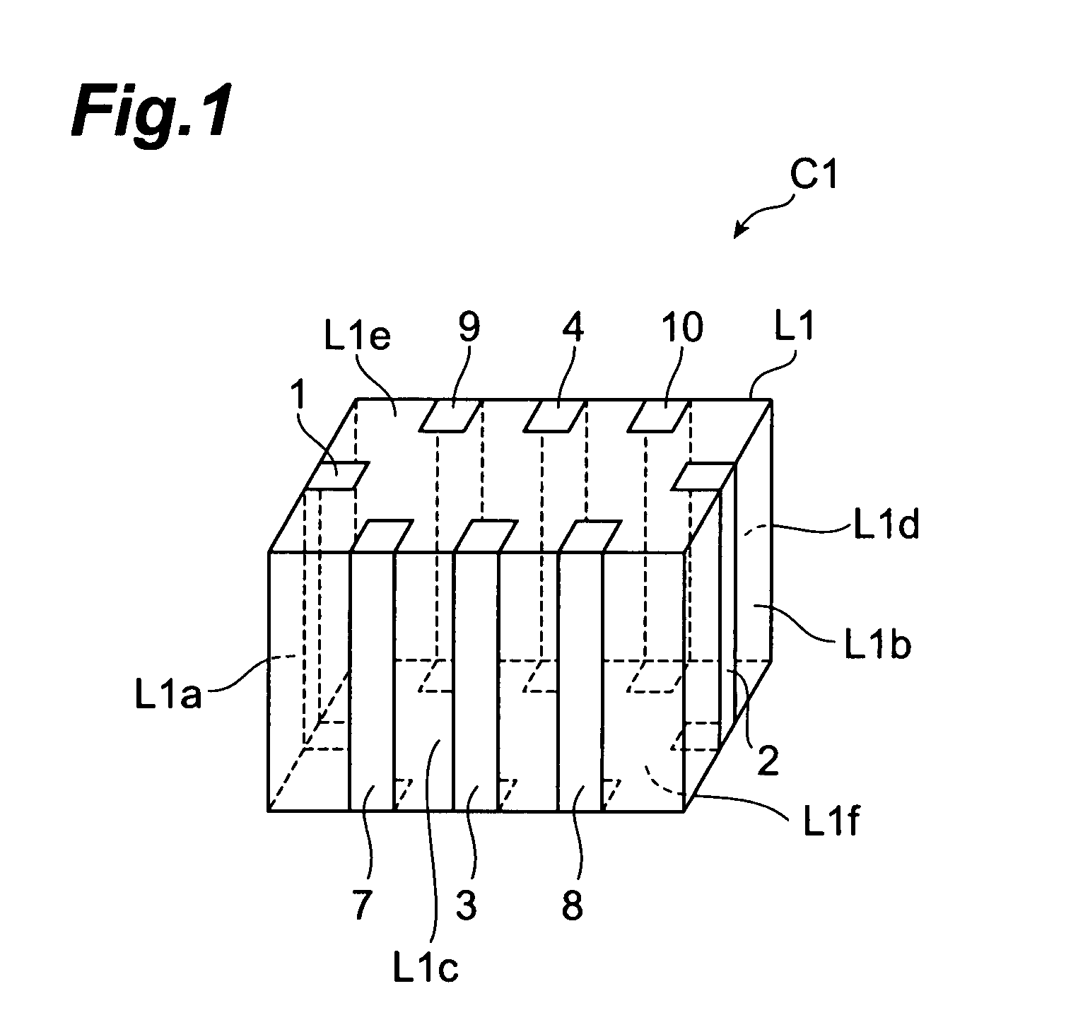
[0026]As shown in FIG. 1, the feedthrough multilayer capacitor C1 in accordance with the first embodiment comprises a capacitor body L1, signal terminal electrodes 1, 2 arranged on the outer surface of the capacitor body L1, grounding terminal electrodes 3, 4 arranged on the outer surface of the capacitor body L1, and connecting conductors 7 to 10 arranged on the outer surface of the capacitor body L1. The signal terminal electrodes 1, 2, grounding terminal electrodes 3, 4, and connecting conductors 7 to 10 are formed, for example, by applying and baking a conductive paste, which c...

second embodiment

[0054]With reference to FIGS. 6 and 7, the structure of feedthrough multilayer capacitor C2 in accordance with a second embodiment will be explained. The feedthrough multilayer capacitor C2 in accordance with the second embodiment differs from the feedthrough multilayer capacitor C1 in accordance with the first embodiment in terms of the structure of grounding terminal electrodes and connecting conductors formed on the capacitor body. FIG. 6 is a perspective view of the feedthrough multilayer capacitor in accordance with the second embodiment. FIG. 7 is an exploded perspective view of the capacitor body included in the feedthrough multilayer capacitor in accordance with the second embodiment.

[0055]As shown in FIG. 6, the feedthrough multilayer capacitor C2 in accordance with the second embodiment comprises a capacitor body L2, signal terminal electrodes 1, 2 arranged on the outer surface of the capacitor body L2, grounding terminal electrodes 3 to 6 arranged on the outer surface of ...


PUM


Abstract

A feedthrough multilayer capacitor comprises a capacitor body, at least two signal terminal electrodes, at least one grounding terminal electrode, and at least one connecting conductor. The capacitor body includes a plurality of insulator layers laminated, a signal inner electrode and a first grounding inner electrode which are arranged so as to oppose each other with at least one insulator layer in between, and a second grounding inner electrode arranged so as to oppose the signal inner electrode or first grounding inner electrode with at least one insulator layer in between. The signal inner electrode is connected to the signal terminal electrodes. The first grounding inner electrode is connected to the connecting conductor. The second grounding inner electrode is connected to the grounding terminal electrode and connecting conductor.

Description

BACKGROUND OF THE INVENTION[0001]1. Field of the Invention[0002]The present invention relates to a feedthrough multilayer capacitor.[0003]2. Related Background Art[0004]Known as this kind of feedthrough multilayer capacitor is one comprising a capacitor body in which insulator layers and inner electrodes for signals and grounding are alternately laminated, and terminal electrodes for signals and grounding formed on the capacitor body (see, for example, Japanese Patent Application Laid-Open No. HEI 01-206615).[0005]On the other hand, power supplies for central processing units (CPUs) mounted in digital electronic devices have been lowering their voltage while increasing their load current. This has made it very difficult for fluctuations in power voltage to be held under a tolerable level, whereby a multilayer capacitor known as decoupling capacitor has been connected to the power supplies. When the load current fluctuates transiently, the multilayer capacitor supplies a current to t...

Claims


Application Information

Patent Timeline
IPC IPC(8): H01G4/005H01G4/228
CPCH01G4/005H01G4/35H01G4/30H01G4/232
Inventor TOGASHI, MASAAKI
Owner TDK CORPARATION
Why Eureka
Try Eureka