
Network expansion enclosure

a network expansion and enclosure technology, applied in the field of enclosures, can solve the problems of not having the necessary rack unit space, the enclosure such as the afc 120, may not have additional rack space or cooling capacity for additional equipment, and the internet service provider is now faced with the difficult problem of incorporating new technology into their current system to provide a wider bandwidth,

Inactive Publication Date: 2008-01-17
APX ENCLOSURES
View PDF19 Cites 34 Cited by
  • Summary
  • Abstract
  • Description
  • Claims
  • Application Information

AI Technical Summary

Benefits of technology

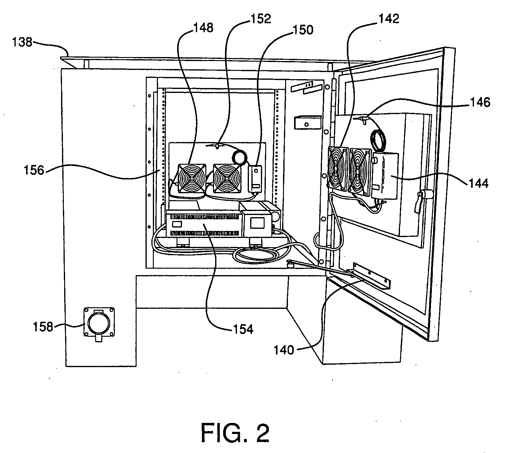
"The invention is an expansion enclosure for a base enclosure that can hold electronic components. The expansion enclosure has a bottom surface with an aperture for connection to the base enclosure, which is affixed to a pad. The expansion enclosure also includes cooling fans, racks for inserting electronic components, access panels for user access, fiber optic cables, telephone cables, electrical cables, and a battery backup unit. The fiber optic cables, telephone cables, and electrical cables are inserted through the generator inlet connector aperture during mounting of the expansion enclosure on the base enclosure. The cooling fans can draw air through the base enclosure and through the generator inlet connector aperture. The technical effects of this invention include improved cooling, increased space for electronic components, and better protection against damage or unauthorized access."

Problems solved by technology

Enclosures such as the AFC 120, while being rugged, may not, however, have additional rack space or cooling capacity for additional equipment.
With the increasing demand for higher Internet speeds, Internet service providers are now faced with the difficult issue of incorporating new technology into their current systems to provide a wider bandwidth.
Current enclosures, such as the AFC 120 are already full with necessary components and cannot provide that necessary rack unit space.
Because the enclosure is in service, it cannot simply be turned off and replaced.
This option, however, could become expensive since the larger enclosures require a new concrete foundation and a “hot switch over.”

Method used


Image

  • Network expansion enclosure
  • Network expansion enclosure
  • Network expansion enclosure

Examples


Embodiment Construction

[0026] In the following, a detailed description of the present invention is given with reference to the drawings.

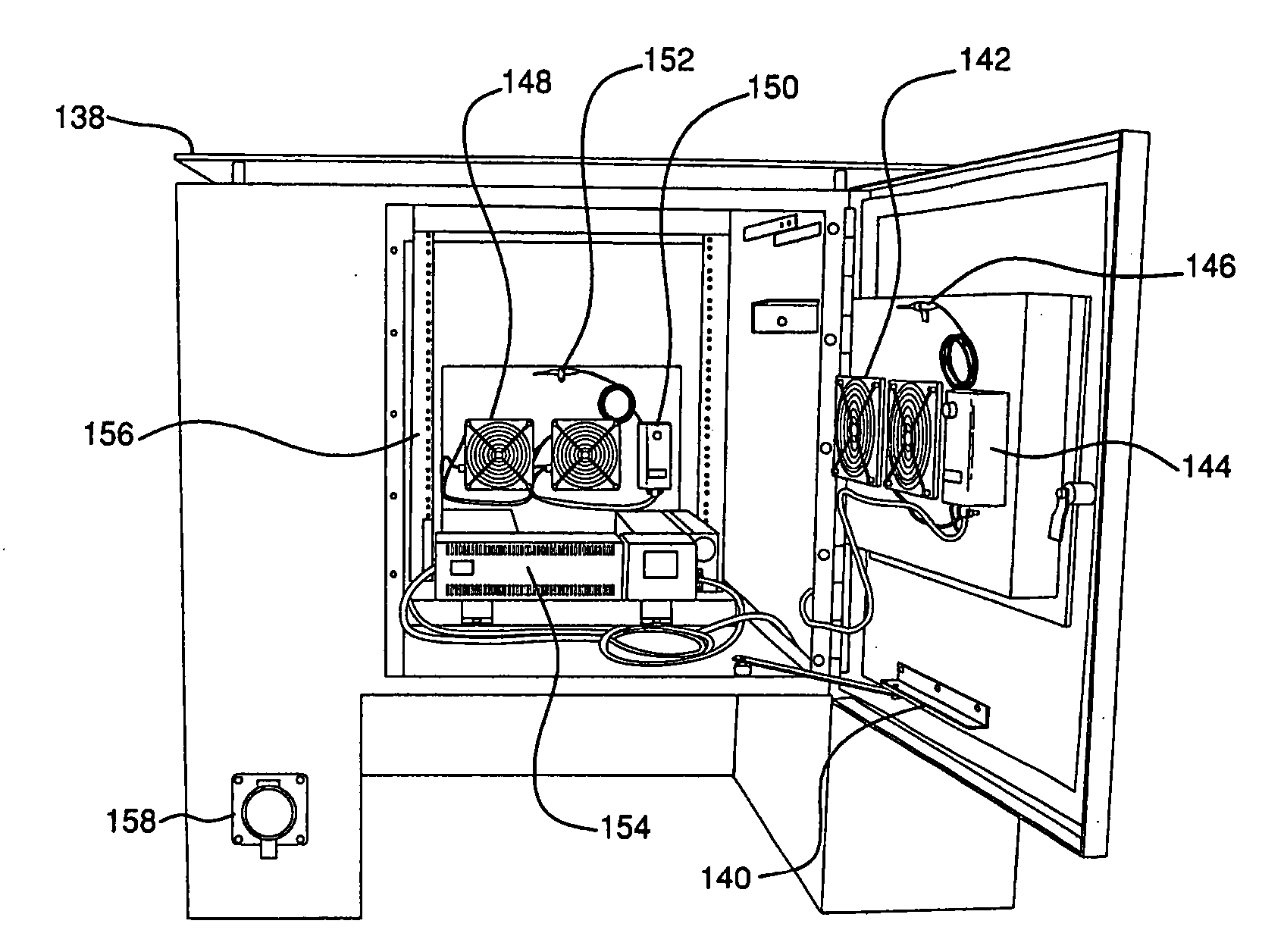
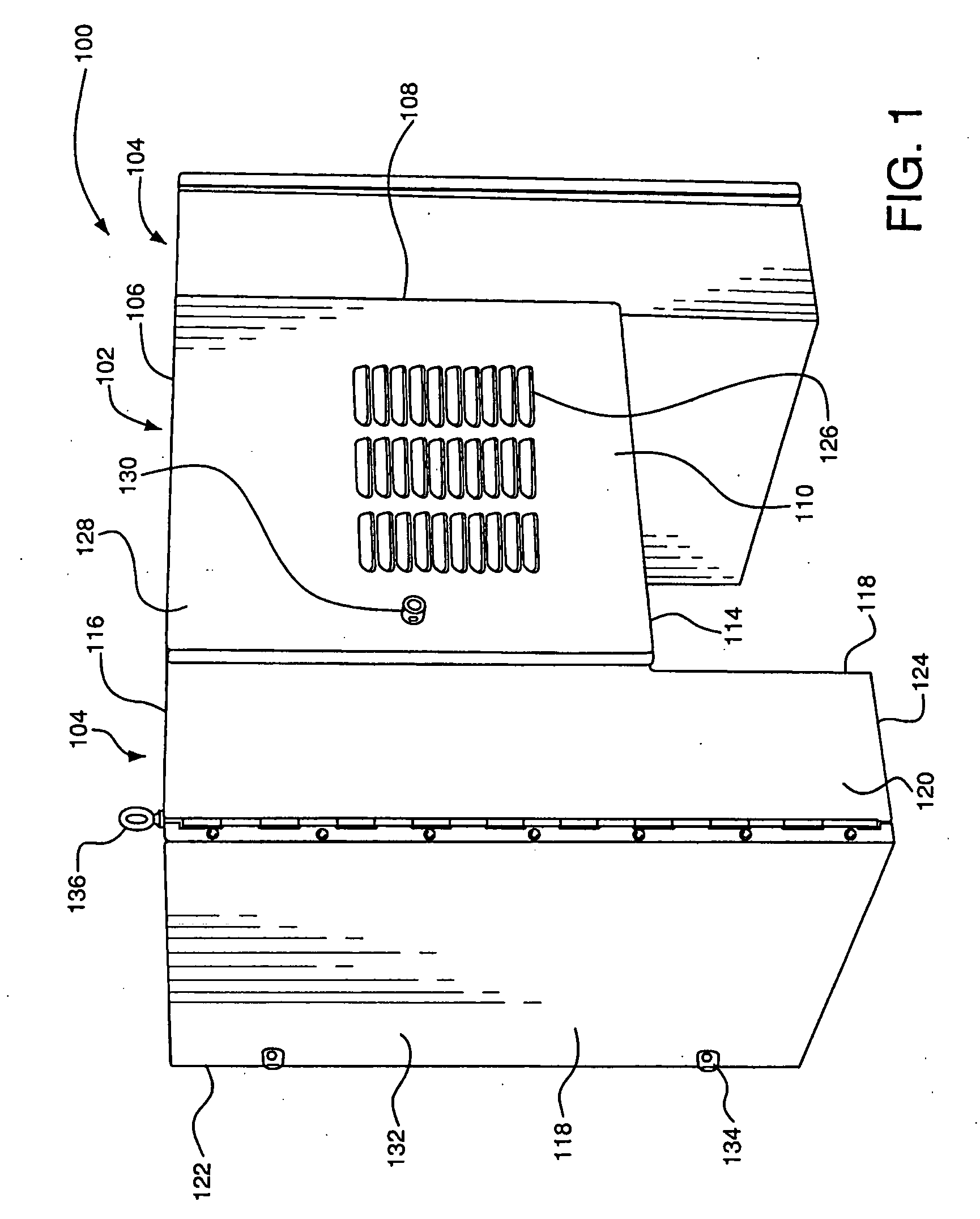
[0027]FIG. 1 is an isometric view of an exemplary expansion enclosure 100 in accordance with the present invention. The exemplary enclosure 100 may include a central portion 102 and two side or saddle portions 104. The central portion 102 may have a top surface 106, two side surfaces 108, a front surface 110, a back surface 112 (see FIG. 2), and a bottom surface 114. The central portion 102 may be in the shape of a cube, for example. The side or saddle portions 104 may also have a top surface 116, two side surfaces 118, a front surface 120, a back surface 122, and a bottom surface 124. The dimensions of the side portions 104 may vary from the central portion 102 such that the side portions 104 when attached to the central portion 102 may extend below the bottom surface 114 of the central portion 102, for example, as depicted in FIG. 1. In an alternative embodiment, the c...


PUM


Abstract

An expansion enclosure assembly includes a bottom surface having apertures formed therein. The bottom surface may be adapted for connection with a base enclosure. The base enclosure includes a generator inlet connector aperture. The expansion enclosure includes cooling fans, racks for insertion of electronic components, access panels for enabling a user to access an interior of the enclosure, fiber optic cables suitable for installation through the generator inlet connector aperture, telephone cables suitable for installation through the generator inlet connector aperture, electrical cables suitable for installation through the generator inlet connector aperture, and a battery backup unit. The fiber optic cables, the telephone cables, and electrical cables of the expansion enclosure may be inserted through the generator inlet connector aperture during mounting of the expansion enclosure on the base enclosure. The cooling fans may draw air from the base enclosure and through the generator inlet connector aperture.

Description

CROSS REFERENCE TO RELATED APPLICATIONS [0001] The subject matter disclosed herein claims priority under 35 U.S.C. § 119(e) to provisional U.S. Patent Application Ser. No. 60 / 809,726, filed May 31, 2006, entitled “NETWORK EXPANSION ENCLOSURE” which is hereby incorporated herein by reference in its entirety.FIELD OF THE INVENTION [0002] The present invention relates generally to an enclosure for the storage of electronic components, and more particularly, for the storage of additional electronic components for a communications network. BACKGROUND OF THE INVENTION [0003] Today, millions of Americans remain connected to the information super highway or Internet through their home computers. With greater software and networking capabilities, the increasing demand for more work output, and the increasing cost of transportation, many working adults are finding it easier to work from their home computers via an Internet connection. [0004] In order to provide Internet access at home, Intern...

Claims


Application Information

Patent Timeline
Patent Type & Authority Applications(United States)
IPC IPC(8): H05K7/20H02B1/00H05K7/14
CPCH05K7/186
Inventor BECKLEY, RONALD WAYNEWRIGHT, ROBERT DAVID JR.
Owner APX ENCLOSURES
Learn More