Method and apparatus

a tubular and tube technology, applied in mechanical apparatus, pipe laying and repair, drilling pipes, etc., can solve the problems of maximum possible length of jumper, crushing of jumper, and compromise of jumper integrity, so as to reduce excess strain

Inactive Publication Date: 2008-01-17
ENERGY EQUIP CORP
View PDF10 Cites 9 Cited by
  • Summary
  • Abstract
  • Description
  • Claims
  • Application Information

AI Technical Summary

Benefits of technology

[0013]The container can have an opening at one end thereof. The opening can have a width less than the inner diameter of the container so that the end is partially enclosed. The partially enclosed end can at least partially retain the coiled tubular within the container and prevent the tubular from slipping out of the container under the effect of gravity. At least a portion of the enclosed end can comprise a frustoconical part. Preferably the frustoconical part is provided around the opening to aid deployment of the tubular. The container can comprise a centrally disposed expandable core. The core can be biased radially outwardly. Such an outwardly biased core enables removal of the lower windings of the coiled tubular without the risk of upper windings falling or collapsing radially inwardly. The container can have a second closed end to which the expandable core can be attached.
[0051]The deployment unit can comprise an open ended container. The container can be rotatable about an axis of coil of the tubular. The container can be supported on bearings, thereby allowing rotation of the container about the coil axis. This arrangement allows the container to passively rotate during deployment of the tubular to alleviate excess strain as the tubular is uncoiled.

Problems solved by technology

When the jumper is unwound from the reel for deployment on the seabed, the jumper can kink and this can compromise the integrity of the jumper if the removal of the jumper from the reel during deployment is not properly controlled.
As a result, the forces that must be applied to maintain the jumper in tension can be considerable and could result in crushing of the jumper at the point where the rollers are gripping.
However, towing the jumper over long distances places high demands on the ROV, which results in a maximum possible length of jumper of around 150 metres.
Thus, deployment of in-field umbilicals can be expensive and time consuming.

Method used


Image

  • Method and apparatus
  • Method and apparatus
  • Method and apparatus

Examples


Embodiment Construction

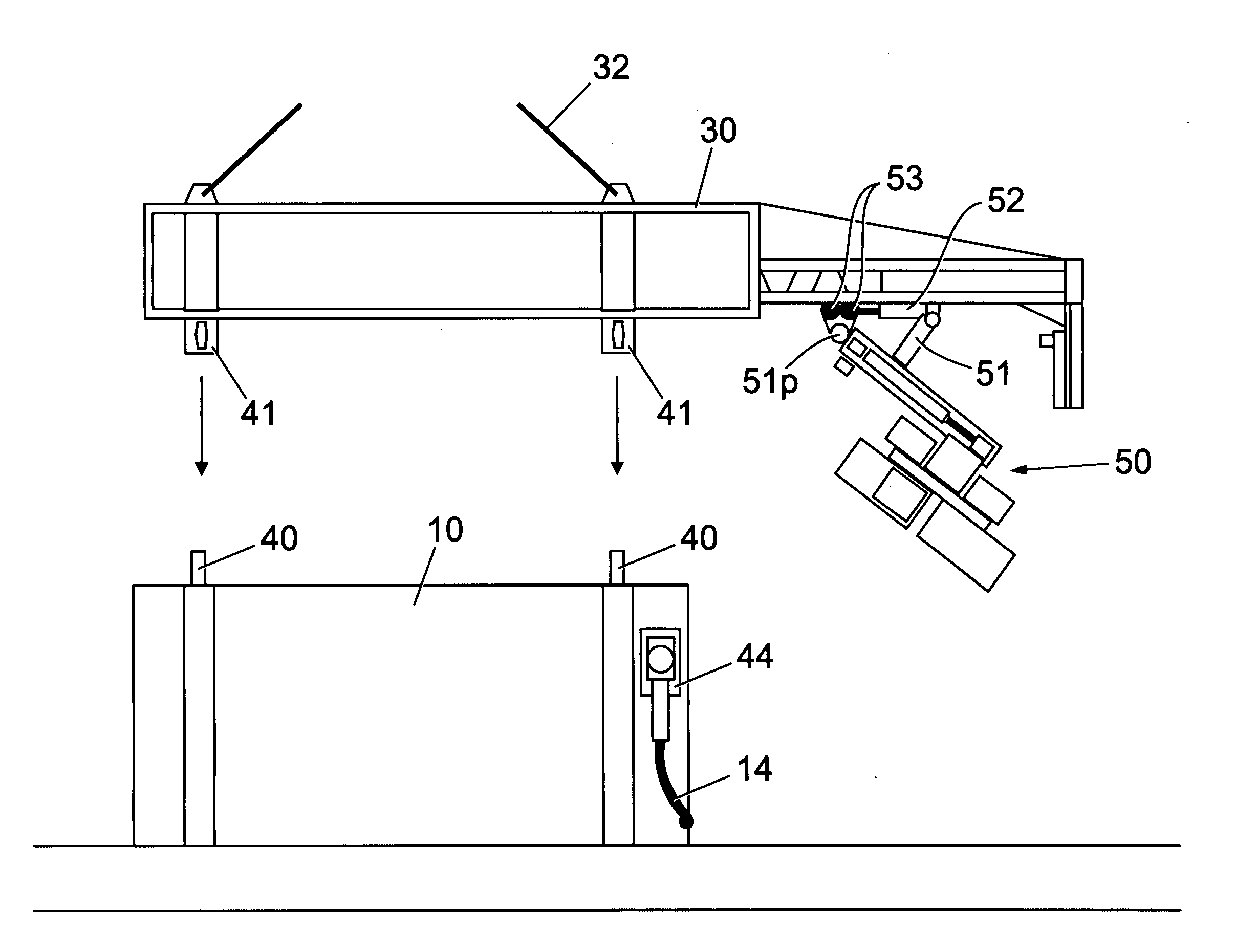
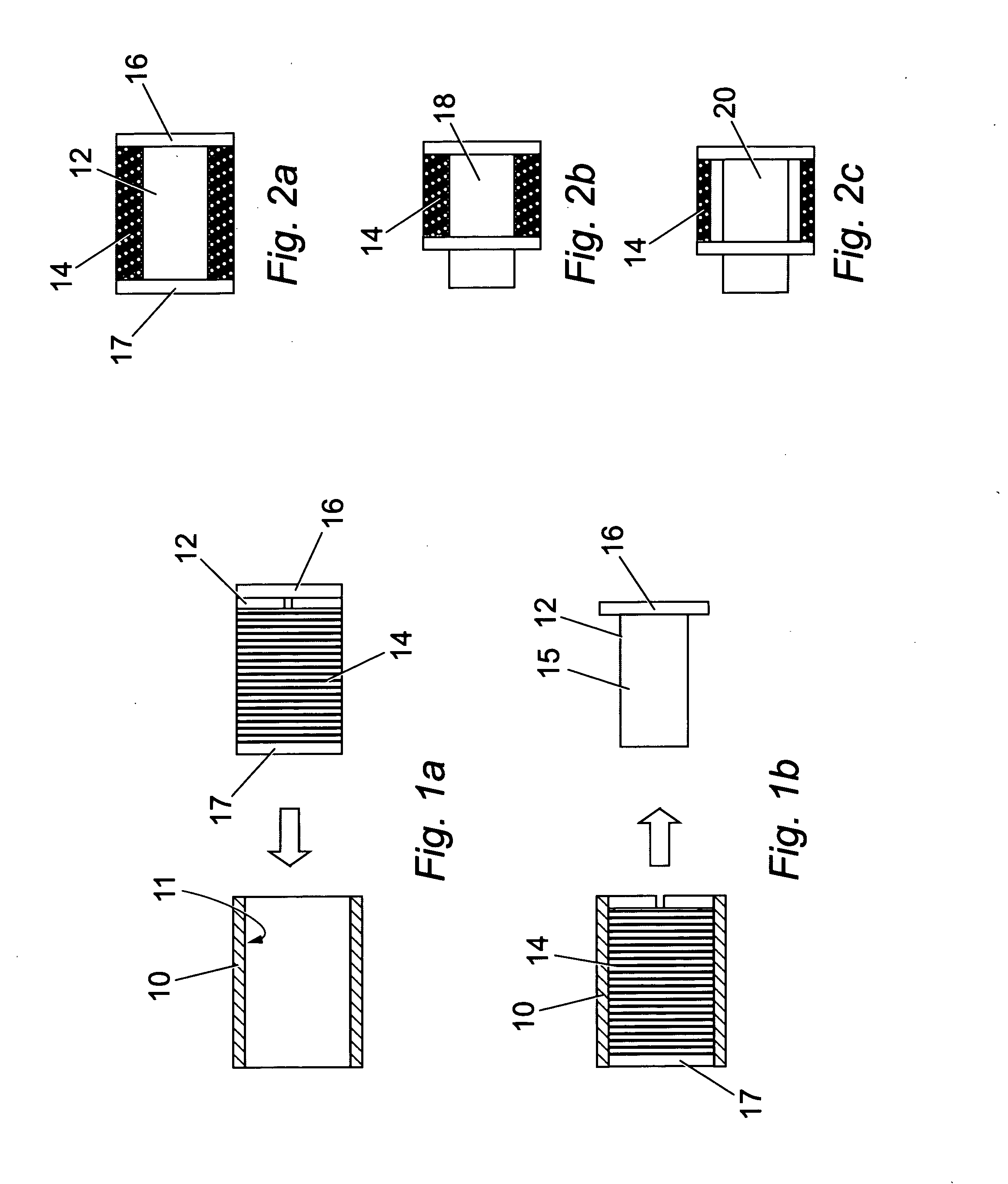
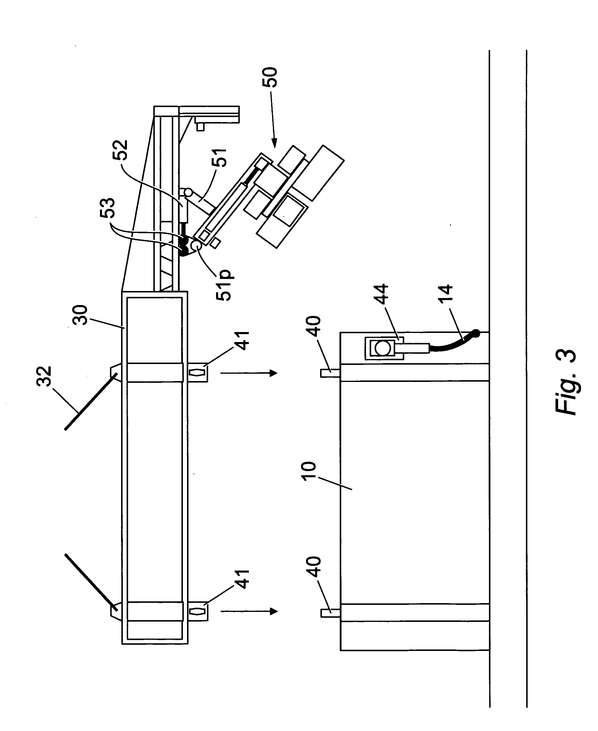
[0080]The method described in the following embodiment requires the tubular to be deployed from within a container or pod. Since conventional methods deploy tubular from a reel, a dedicated process of loading a tubular within a pod is shown in FIGS. 1a and 1b. Loading of the tubular within the pod occurs prior to deployment of the tubular along the predetermined path, which according to the first embodiment lies between two subsea installations.

[0081]FIG. 1a shows a substantially cylindrical hollow pod 10 having an inner diameter 11 which can accommodate a reel 12. The reel 12 has a core 15 of reduced diameter, an end plate 16 and a detachable end plate 17.

[0082]A jumper 14 is coiled around the core 15 of the reel 12 as shown in the cross-sectional view of FIG. 2a. The jumper 14 is installed on the reel 12 following the manufacturing process. According to the first described embodiment, the jumper 14 is installed on the reel with a degree of reverse twist to compensate for the degre...


PUM


Abstract

The invention provides an apparatus and a method of deploying a tubular along a predetermined path. The method includes the steps of: coiling a tubular; accommodating the tubular in a deployment unit such that at least a portion of the coiled tubular is biased radially outwardly against the deployment unit; and deploying the tubular from the deployment unit along the predetermined path. The tubular can be deployed in a fluid along a predetermined path by: independently suspending the deployment unit in the fluid; and moving the deployment unit adjacent the predetermined path and simultaneously deploying the tubular along the predetermined path. The apparatus for deploying a tubular can comprise a deployment facilitator for facilitating deployment of the coiled tubular. The tubular can be arranged to feed into the deployment facilitator in use, and the deployment facilitator can be adapted to substantially reverse the coil bend of the tubular.

Description

FIELD OF THE INVENTION[0001]The present invention relates to a method and an apparatus for deploying a tubular along a pre-determined path. In particular, the method and apparatus is useful for subsea applications and for deployment of tubulars including jumpers comprising electrical power cables, communications cables and / or hydraulic lines.BACKGROUND OF THE INVENTION[0002]Subsea installations used in the oil and gas industry are often inter-connected by umbilicals, jumpers and other tubulars, which provide a conduit for electrical power, communications, hydraulic power and fluids between the various subsea installations. Conventionally, cables and tubulars have been installed from a reel located on a pipeline laying vessel on the surface of the sea. A remotely operated vehicle (ROV) typically carries each end of the jumper and flies it into position. If a jumper is installed onto a reel, bends are imposed on the jumper. When the jumper is unwound from the reel for deployment on th...

Claims


Application Information

Patent Timeline
Patent Type & Authority Applications(United States)
IPC IPC(8): F16L1/12
CPCF16L1/203B65H75/362E21B19/22
Inventor WEBSTER, DAVID
Owner ENERGY EQUIP CORP
Why Eureka
Try Eureka