Hemostatic bandage and method of use

a hemostatic bandage and bandage technology, applied in the field of hemostatic bandage, can solve the problems of significant discomfort at the puncture site of the patient, significant failure rate of late bleeding and hematoma formation, and inability to readily seal the puncture with the application of brief pressure, so as to facilitate the insertion of the puncture tract, achieve hemostasis, and promote coagulation.

Inactive Publication Date: 2008-01-17
INNOVASA CORP
View PDF31 Cites 28 Cited by
  • Summary
  • Abstract
  • Description
  • Claims
  • Application Information

AI Technical Summary

Benefits of technology

[0015] In some embodiments, the bandage is composed of polymeric foam. The polymeric foam is hydrophilic polyurethane foam in some embodiments. The bandage can have many shapes, but typically has a shape that facilitates its insertion into the puncture tract. For instance, in some embodiments, the bandage has a tapered tip.
[0016] Also, in some embodiments, the bandage includes or is coated with one or more materials that are designed to promote coagulation and thereby achieve hemostasis. For example, in some embodiments, the bandage includes, is coated with, or is entirely composed of Chitosan. Chitosan may be incorporated on and into the foam bandage by means of dipping the bandage into a Chitosan solution. In some embodiments, the foam bandage is lyophilized after dipping it into the Chitosan solution.

Problems solved by technology

However, when punctures are created with larger caliber apparatus (such as catheters) in the high-pressure environment of arteries, the puncture created will not readily seal with the application of brief pressure.
Prolonged external pressure may be required for fifteen to thirty minutes and may lead to substantial discomfort at the puncture site for the patient and / or a significant failure rate with late bleeding and hematoma formation.
Such wounds also typically do not readily seal with the application of brief pressure.
However, this is often inadequate to effectively reduce or eliminate bleeding due to puncture or disruption of blood vessels and organs.
The prior apparatus lack both a mechanism for precise positioning of a pressure-generating component against a puncture tract and a structure designed to optimize the pressure that is to be applied to such a site.
Consequently, such an apparatus would reduce patient discomfort, staff time and the unfavorable failure rate associated with vascular hemostasis and the risk of hemotoma formation.

Method used


Image

  • Hemostatic bandage and method of use
  • Hemostatic bandage and method of use
  • Hemostatic bandage and method of use

Examples


Embodiment Construction

[0038] In the following description, numerous details are set forth to provide a better understanding of the various embodiments of the invention. However, one of reasonable skill in the art will realize that the invention may be practiced without the use of the specific details presented herein. In some instances of describing the invention, well-known structures and apparatus may be shown in block diagram form to avoid obscuring the description of the invention with unnecessary detail. Therefore, the examples provided herein for clarification and understanding should not be read into and thereby limit the language of the claims.

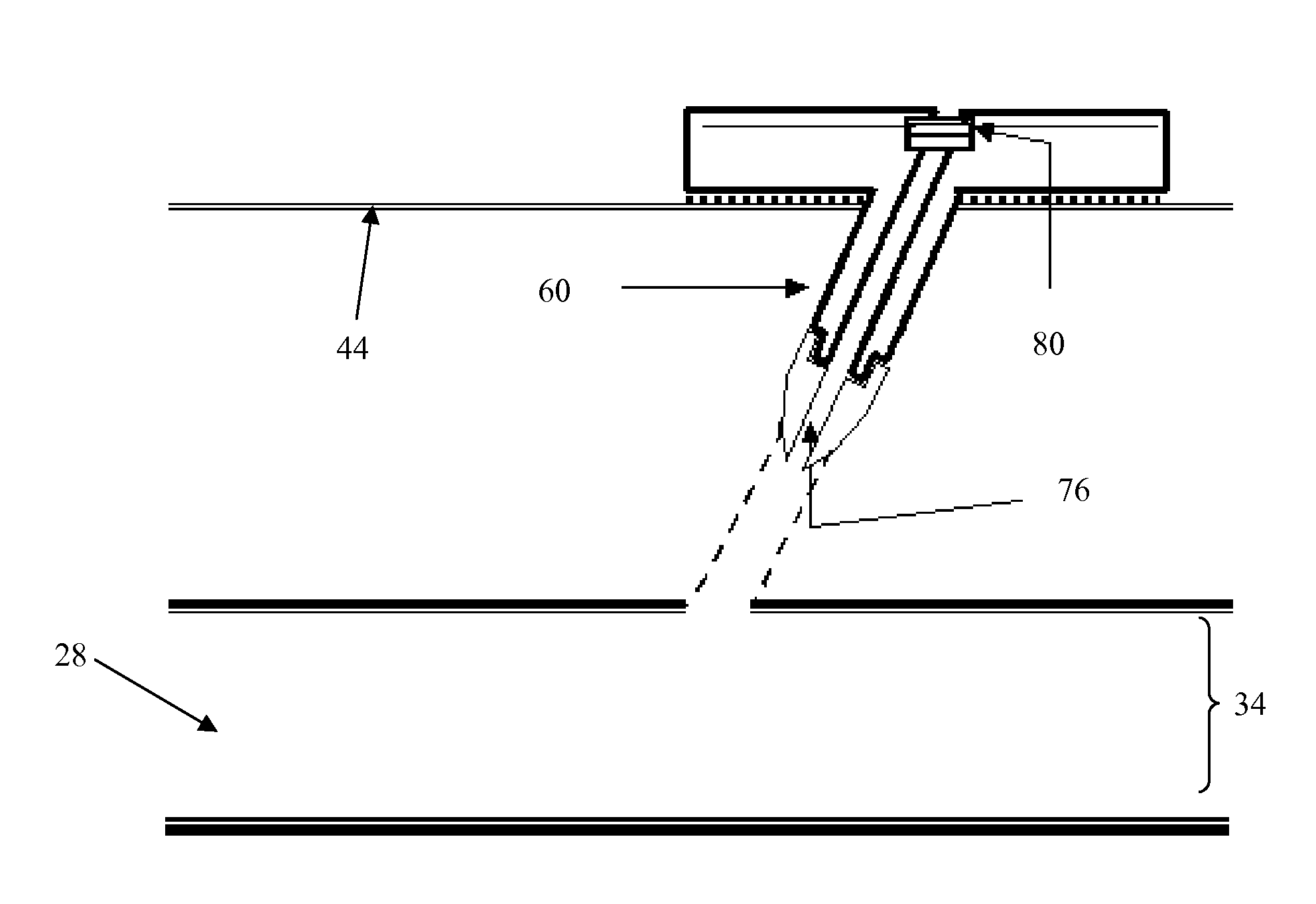
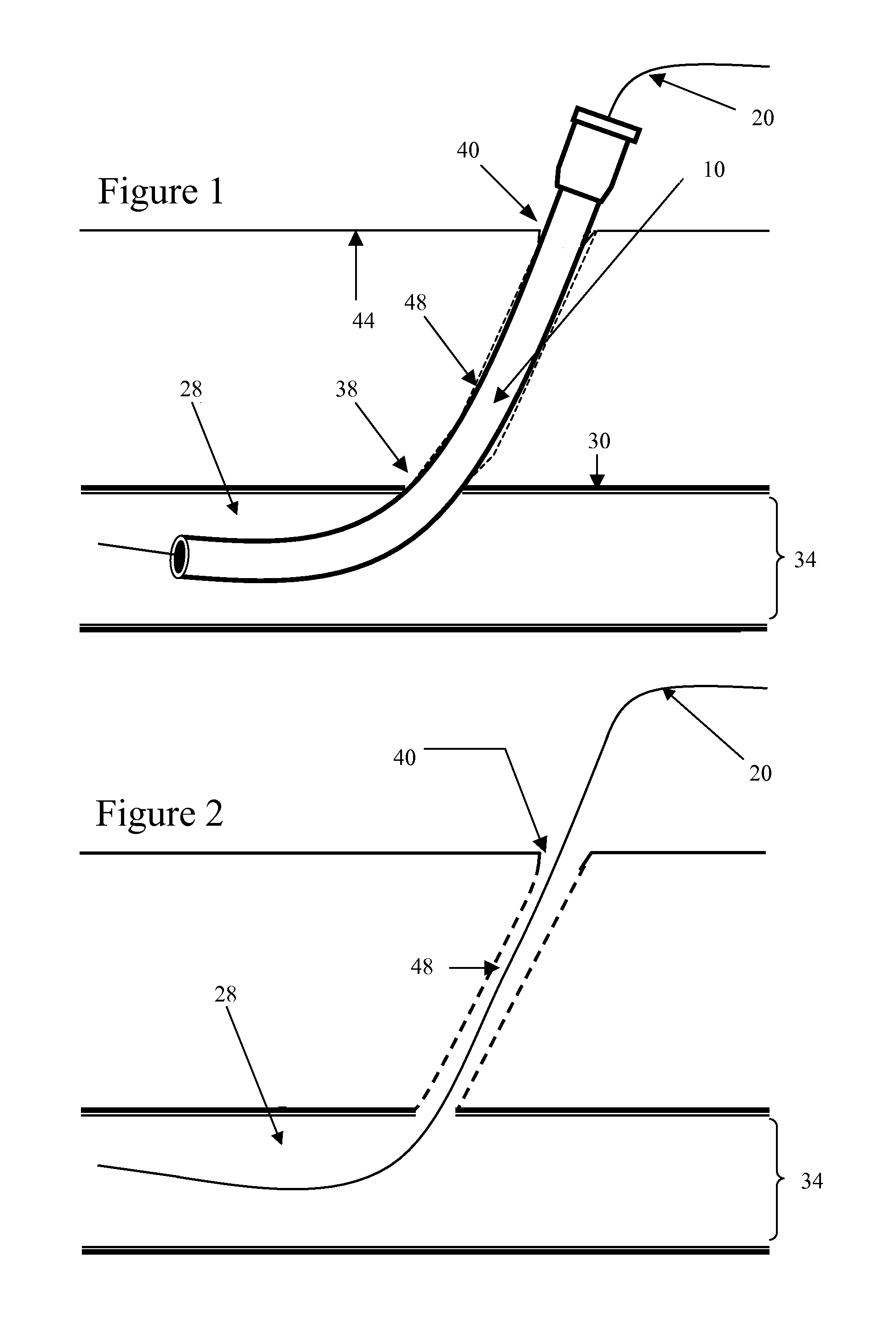
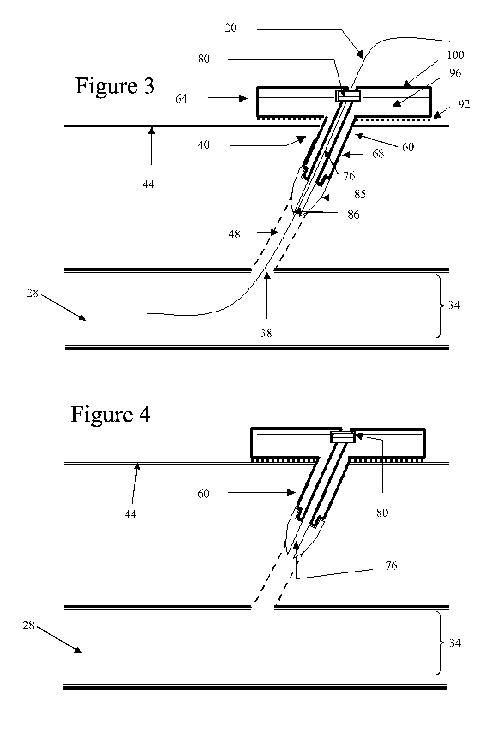
[0039] Some embodiments of the invention provide an apparatus for achieving hemostasis in a puncture tract. Such a tract might have been created during a medical procedure or operation. Alternatively, the tract might be a result of a traumatic injury (e.g., injury that occurred outside of a hospital) that created a traumatic wound, such as a bullet wound, ...


PUM


Abstract

Some embodiments of the invention provide an apparatus for achieving hemostasis in a puncture tract. Such a tract might have been created during a medical procedure, operation or a traumatic injury. In some embodiments, the apparatus includes a bandage for placement within the puncture tract. The apparatus also includes a stem with a distal end. In some embodiments, the bandage couples to the distal end of the stem. In other embodiments, the bandage couples to the entire length of the stem. Along with the bandage, the stem's distal end is at least partially inserted into the puncture tract in some embodiments. In other embodiments, only the bandage is inserted into the puncture tract. The bandage is typically maintained within the puncture tract until hemostasis is achieved. Once hemostasis has been achieved, the operator removes the bandage from the puncture tract.

Description

CLAIM OF BENEFIT [0001] This application is a continuation-in-part of U.S. patent application Ser. No. 11 / 245,956, filed on Oct. 7, 2005, and is a continuation-in-part of U.S. patent application Ser. No. 11 / 332,784, filed on Jan. 12, 2006. Both these non-provisional applications claim the benefit of U.S. Provisional Application 60 / 693,706, filed on Jun. 24, 2005, and both these non-provisional applications claim the benefit of U.S. Provisional Application 60 / 688,510, filed on Jun. 7, 2005. The nonprovisional application Ser. Nos. 11 / 245,956 and 11 / 332,784 are incorporated herein by reference.FIELD OF THE INVENTION [0002] The invention is directed towards a hemostatic bandage and a method of using the same. BACKGROUND OF THE INVENTION [0003] Numerous medical diagnostic and therapeutic procedures require access to the internal organs of a living organism. Some of these procedures can be performed without traditional surgical incisions by utilizing catheter-based apparatus to enter blo...

Claims


Application Information

Patent Timeline
Patent Type & Authority Applications(United States)
IPC IPC(8): A61F13/02
CPCA61B17/0057A61B17/085A61B2017/00654A61B2017/00659A61B2017/00884A61M2039/0276A61B2017/22038A61F13/0203A61M39/0247A61M2039/0258A61B2017/00893
Inventor BERGIN, PATRICK J.WENSEL, JEFFREY P.
Owner INNOVASA CORP
Why Eureka
Try Eureka