Accurate dynamic gravity measurement method and apparatus

a dynamic gravity and measurement method technology, applied in the direction of measuring devices, speed/acceleration/shock measurement, instruments, etc., can solve the problems of reducing the accuracy of gravity measurements obtained, and affecting the accuracy of gravity measurements

Inactive Publication Date: 2008-01-17
MICRO G LACOSTE
View PDF3 Cites 22 Cited by
  • Summary
  • Abstract
  • Description
  • Claims
  • Application Information

AI Technical Summary

Benefits of technology

[0017] The present invention involves calibrating relative gravity measurement signals from relative gravimeters on a periodic basis with absolute gravity measurement signals from an absolute gravimeter, to make the gravity measurements from the relative gravimeters comparable in accuracy to the gravity

Problems solved by technology

An absolute gravimeter is a technically sophisticated, more expensive and physically larger instrument than a relative gravimeter, at the present time.
In a relative gravimeter, the spring-like device which suspends the known mass is susceptible to many influences that degrade the accuracy of the gravity measurements obtained.
Relative gravimeters are generally less reliable and less accurate than absolute gravimeters for measuring temporal changes in gravity.
The effect of changes in temperature, pressure, tare or drift can mask any change in the magnitude of gravity, making it impossible to accurately measure small changes in gravity.
While the accuracy of the gravity measurements obtained by using an absolute gravimeter is very high compared to the accuracy in measurements obtained by using a relative gravimeter, the sensitivity and complexity of the absolute gravimeter has made it impossible or very difficult to employ a gravimeter in any location other than in a controlled scientific laboratory where all of the environmental influences can be controlled.
Only recently have field-usable absolute gravimeters been developed, but such field-usable absolute gravimeters are expensive, in the neighborhood of US $300,000-500,000, which is roughly five times the price for a relative gravimeter.
Furthermore, the use of such field-usable absolute gravimeters is tedious and time-consuming.
The relatively high cost of field-usable absolute gravimeters has had the practical consequence of requiring a single absolute gravimeter to be moved from one location to another, in order to acquire

Method used


Image

  • Accurate dynamic gravity measurement method and apparatus
  • Accurate dynamic gravity measurement method and apparatus
  • Accurate dynamic gravity measurement method and apparatus

Examples


Embodiment Construction

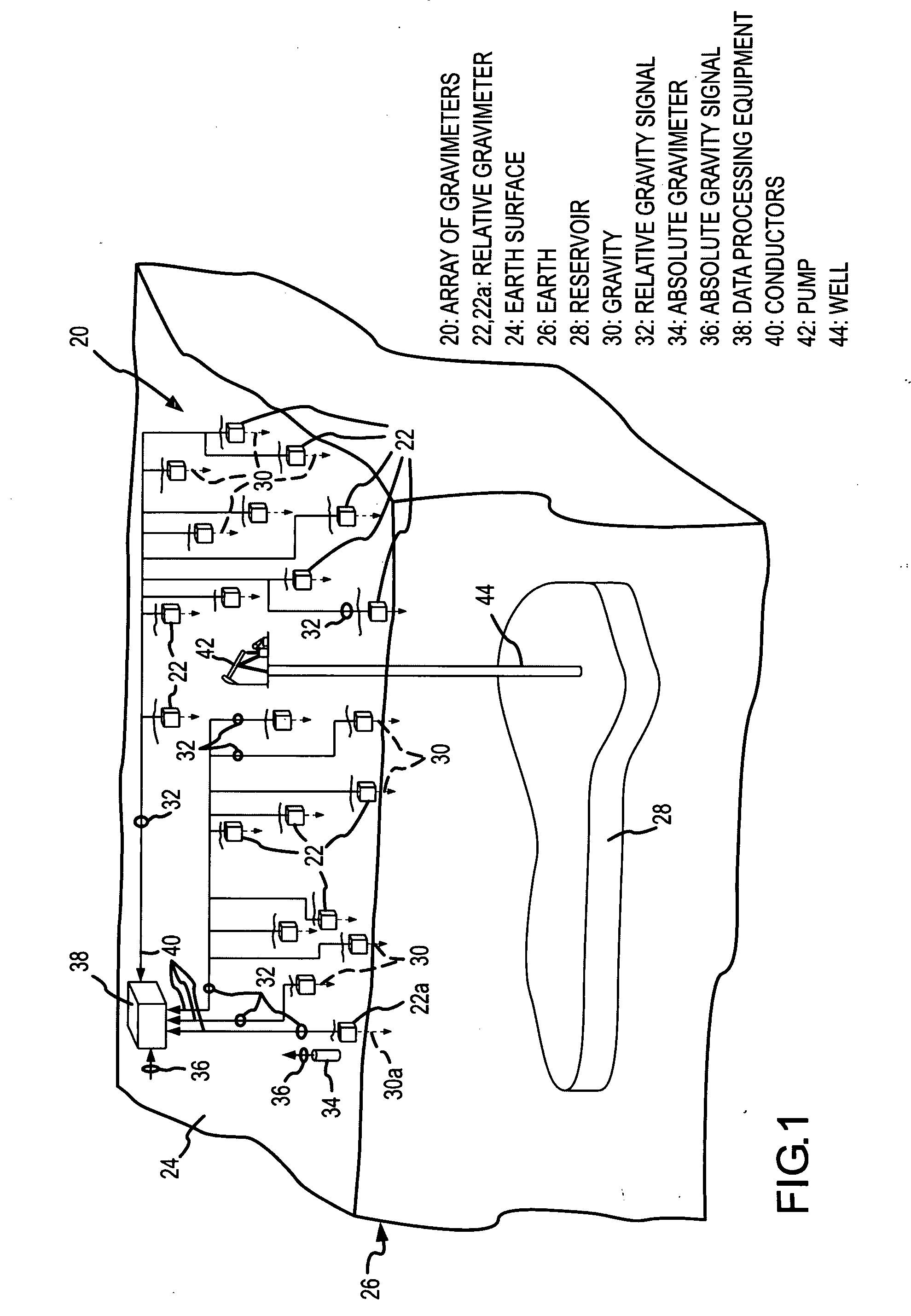
[0028] The invention is implemented by use of an array 20 of relative gravimeters 22, shown in FIG. 1. Each relative gravimeter 22 is located on a surface 24 of the earth 26 or buried slightly below the earth surface 24 (FIG. 3). In addition, some of the relative gravimeters 22 may be buried considerably below the earth surface 24 (FIG. 4) or elevated substantially above the earth surface 24 (FIG. 5). Each relative gravimeter 22 is positioned at a predetermined location above a subsurface or subterranean reservoir 28 or other subsurface structure or formation whose density changes are to be monitored by gravity measurements from the relative gravimeters 22. Each of the relative gravimeters 22 measures the vertical component of the magnitude of gravity 30 at its particular position and supplies a relative gravity measurement signal 32 related to the vertical component of measured gravity 30. The numbers and locations of the relative gravimeters 22 are selected to provide enough gravi...


PUM


Abstract

Gravity information for a gravity survey is obtained by using an array of relative gravimeters whose relative gravity measurement signals have been calibrated by using an absolute gravimeter to approximate absolute gravity measurements.

Description

[0001] This invention relates to the measurement of the magnitude of gravity. More particularly, this invention relates to a new and improved method and apparatus that uses relatively inexpensive relative gravimeters whose relative gravity measurement signals are adjusted into calibrated relative gravity measurements that are comparable in accuracy to absolute gravity measurements, and supplying those calibrated relative gravity measurements on a real-time, continuous and dynamic basis without incurring the significant cost or impracticality of using absolute gravimeters to obtain such gravity information. BACKGROUND OF THE INVENTION [0002] The gravitational force of attraction between two massive bodies is the force which results from the inherent natural attraction between the two bodies. The magnitude of the gravitational force is related to the mass of the bodies and is inversely related to the separation distance between centers of mass of the bodies. Gravity is measured as acc...

Claims


Application Information

Patent Timeline
IPC IPC(8): G01V7/00G01R35/00
CPCG01V13/00G01V7/00
Inventor NIEBAUER, TIMOTHY M.NIND, CHRISTOPHER J.M.
Owner MICRO G LACOSTE
Why Eureka
Try Eureka