Evaluation system and method

a technology of evaluation system and evaluation method, applied in the field of evaluation system and its evaluation method, can solve the problems of limiting the number of rewrites in flash memory, hindering adequate debugging, and limiting the number of rewrites, so as to improve the reliability of a program

Inactive Publication Date: 2008-01-17
NEC ELECTRONICS CORP
View PDF6 Cites 24 Cited by
  • Summary
  • Abstract
  • Description
  • Claims
  • Application Information

AI Technical Summary

Benefits of technology

[0020]An evaluation system and its evaluation method according to the present invention enable the faithful reproduction of an error which occurs in a storage unit and the improvement of the reliability of a program.

Problems solved by technology

However, there is a limit to the number of rewrites in a flash memory.
The limit to the number of rewrites can hinder the adequate debugging.
However, a flash memory can sometimes fail to write data normally depending on conditions such as an operating voltage and an operating temperature.
If the verification process detects an error in a flash memory, error handling such as performing another writing data in the same area or performing another writing after changing a data write region to a different area is carried out.
On the other hand, if an error is detected in the verification process, error handling is performed (S108).
However, a write error which occurs in a flash memory happens under certain conductions and it does not always happen.
When executing the processing A and the processing B individually, it is necessary to perform debugging for the processing A and debugging for the processing B separately and further to combine the processing A and the processing B, which complicates the procedure.
Further, when combining the program for the processing A and the program for the processing B, it is unable to verify the combining portion of the processing A and the processing B, which causes a human error or the like to degrade the reliability of the program.
If the program is kept executed until a write error occurs, it is unable to know the timing when an error occurs and therefore the operating efficiency decreases significantly.
Thus, the verification on the evaluation system cannot be reproduced faithfully and therefore it is unable to perform accurate program debugging, thus degrading the reliability of the program.
The error generator thereby generates a dummy error signal during the execution of a program.

Method used


Image

  • Evaluation system and method
  • Evaluation system and method
  • Evaluation system and method

Examples


first embodiment

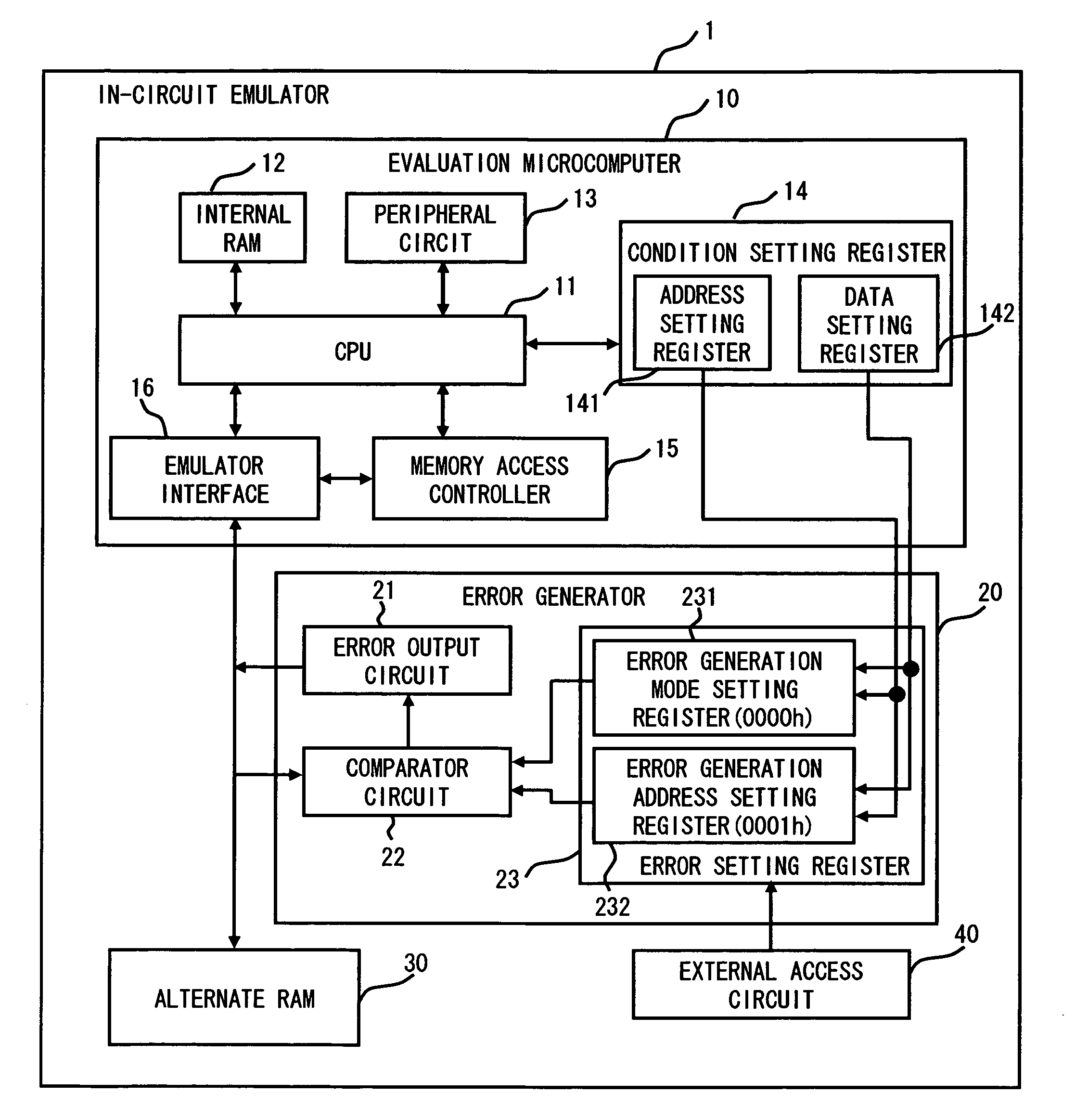
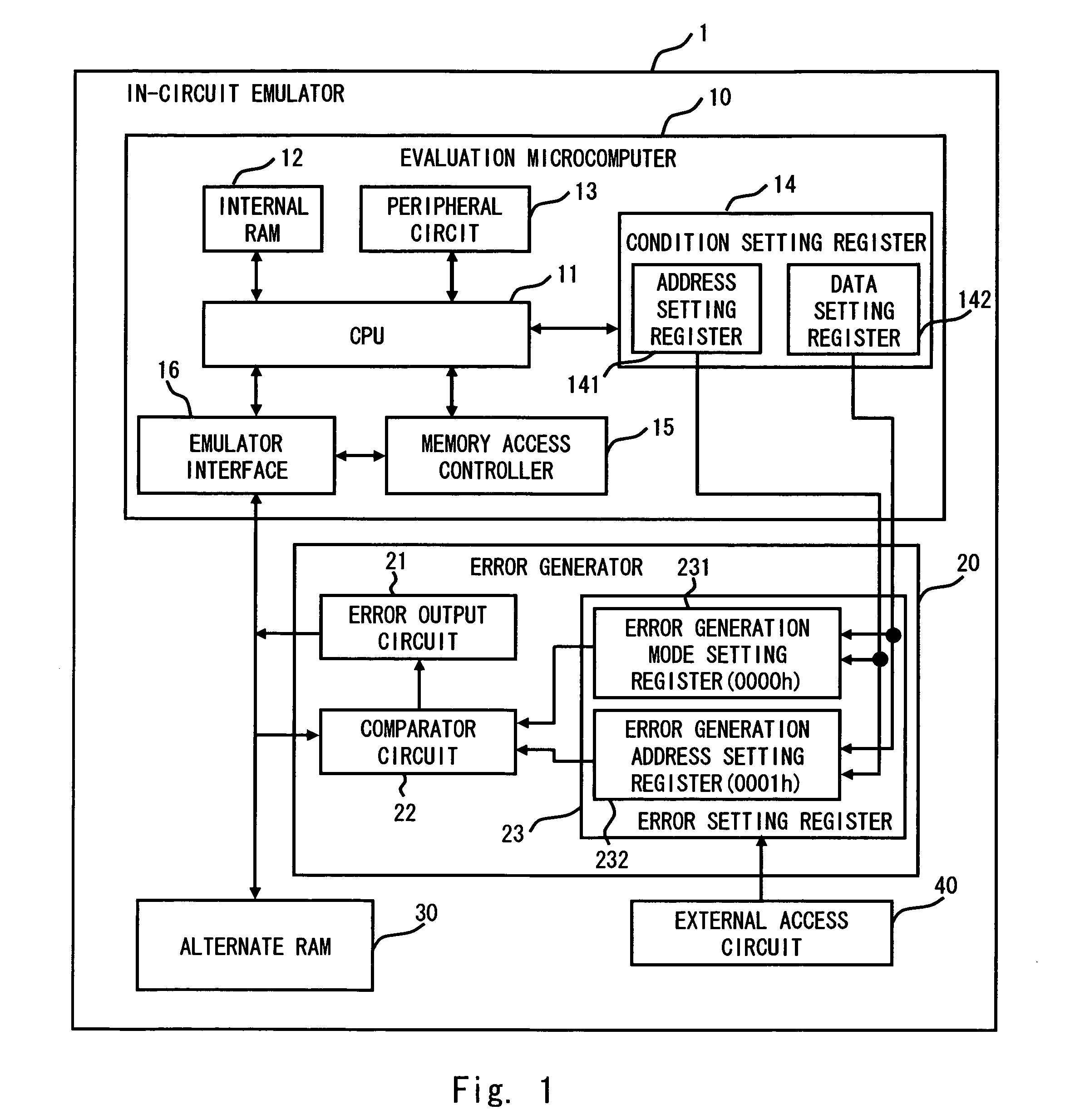
[0040]Embodiments of the present invention are described hereinafter with reference to the drawings. An evaluation system according to one embodiment of the present invention performs execution and evaluation of a program such as flash firmware. The evaluation of a program is a process of finding and correcting a bug in a program to be evaluated, which is referred to hereinafter also as debugging. The evaluation system 1 is also called an in-circuit emulator, and a plurality of semiconductor devices are placed on an evaluation board. In the present invention, an evaluation microcomputer, an error generator, an alternate RAM, and an external access circuit are placed as semiconductor devices.

[0041]FIG. 1 is a block diagram of the evaluation system 1 according to a first embodiment of the present invention. Referring to FIG. 1, the evaluation system 1 includes an evaluation microcomputer 10, an error generator 20, an alternate RAM 30, and an external access circuit 40. The evaluation ...

second embodiment

[0081]FIG. 9 is a block diagram of an evaluation system 2 according to a second embodiment of the present invention. In FIG. 9, the same elements as in the first embodiment are denoted by the same reference symbols and not described in detail herein.

[0082]The evaluation system 2 of the second embodiment is different from the evaluation system 1 of the first embodiment in the configuration of the error generator. The error generator 20 of the first embodiment generates an error signal based on a mode signal and a read address. On the other hand, an error generator 50 of the second embodiment generates an error signal based on a mode signal, a read address and the number of accesses to the read address.

[0083]Referring to FIG. 9, the error generator 50 includes an access counter 54 and an access number setting register 531 in addition to the configuration of the error generator 20. The access number setting register 531 is defined within the area of an error setting register 53. FIG. 1...

third embodiment

[0094]FIG. 12 is a block diagram of an evaluation system 3 according to a third embodiment of the present invention. In FIG. 12, the same elements as in the first embodiment are denoted by the same reference numerals and not described in detail herein.

[0095]The evaluation system 3 of the third embodiment is different from the evaluation system 1 of the first embodiment in the configuration of the error generator. The error generator 20 of the first embodiment includes a register that stores an error generation mode and an error generation address to generate an error. On the other hand, an error generator 60 according to the third embodiment includes an error setting RAM 62 that has the same number of error generation mode storage areas as the number of addresses of the alternate RAM 30.

[0096]As shown in FIG. 12, the error generator 60 includes a comparator circuit 61 and the error setting RAM 62. The error setting RAM 62 is described firstly. FIG. 13 shows the relationship between ...


PUM


Abstract

An evaluation system includes a storage unit, a microcomputer for outputting a read address to the storage unit and executing reading, and an error generator for generating an error signal based on a mode signal and the read address that are transmitted between the storage unit and the microcomputer and outputting the error signal. The microcomputer determines read data received from the storage unit as an error regardless of the read data when the error signal indicates an error in the read data.

Description

BACKGROUND OF THE INVENTION[0001]1. Field of the Invention[0002]The present invention relates to an evaluation system and its evaluation method and, particularly, to an evaluation system which includes an error generator that reproduces an error which occurs in a storage unit used in a semiconductor device and its evaluation method.[0003]2. Description of Related Art[0004]Some microcomputers include a storage unit for storing a control program, a user program or the like. Recently, a flash memory is widely used as such a storage unit. A flash memory allows the modification of a stored program even after a semiconductor device is manufactured. It is therefore effective in the production of small batches of a variety of semiconductor devices.[0005]A flash memory is also used to store data in addition to storing a user program or the like because stored information is not erased upon power-off. In such a case, it is necessary to write control software such as flash firmware that contro...

Claims


Application Information

Patent Timeline
Patent Type & Authority Applications(United States)
IPC IPC(8): G11C29/00
CPCG06F11/366G06F11/2215
Inventor IDE, TAKETOSHI
Owner NEC ELECTRONICS CORP
Why Eureka
Try Eureka