Automatic winder for an inside brushless stator

a brushless, automatic technology, applied in the direction of dynamo-electric machines, magnetic bodies, electrical apparatuses, etc., can solve the problems of time and labor in manufacturing machines, and the cost of machines is high

Inactive Publication Date: 2008-01-24
JONES ROBERT M
View PDF3 Cites 9 Cited by
  • Summary
  • Abstract
  • Description
  • Claims
  • Application Information

AI Technical Summary

Benefits of technology

[0009]In yet another aspect, the apparatus has a locking ring with a locking ring aperture. The locking ring is placed over the stator loader. The stator is placed in the collet and aligned with the locking ring aperture. The stator is held in the stator holder.
[0010]In a further aspect, the apparatus further comprises a controller. The controller is configured to control the movement of the first movable member and the second rotating member.
[0011]According to another embodiment, the ap

Problems solved by technology

Manufacturing machines typically involve time and labor in order to wind or wrap wires around and/or within the axial slots of a stator.
Such machines ar

Method used


Image

  • Automatic winder for an inside brushless stator
  • Automatic winder for an inside brushless stator
  • Automatic winder for an inside brushless stator

Examples


Embodiment Construction

[0029]A description of example embodiments of the invention follows.

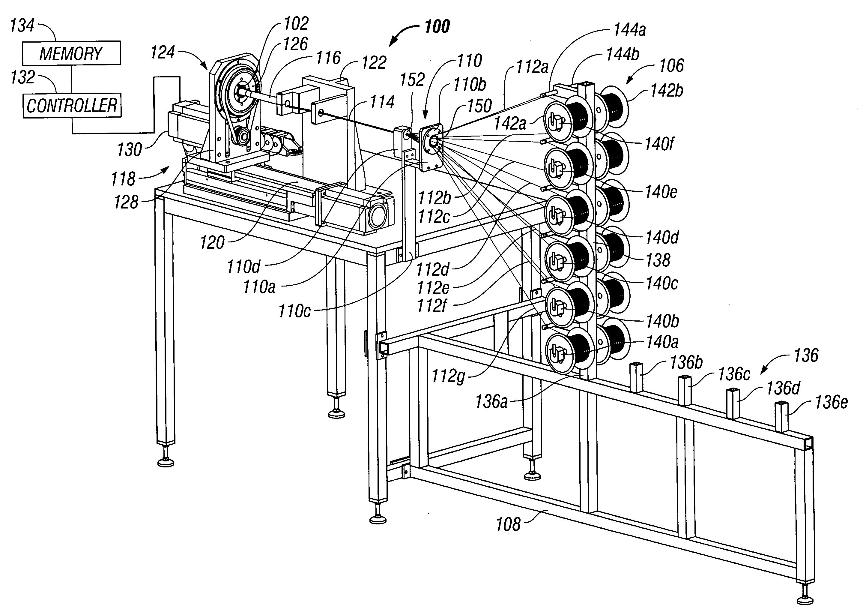
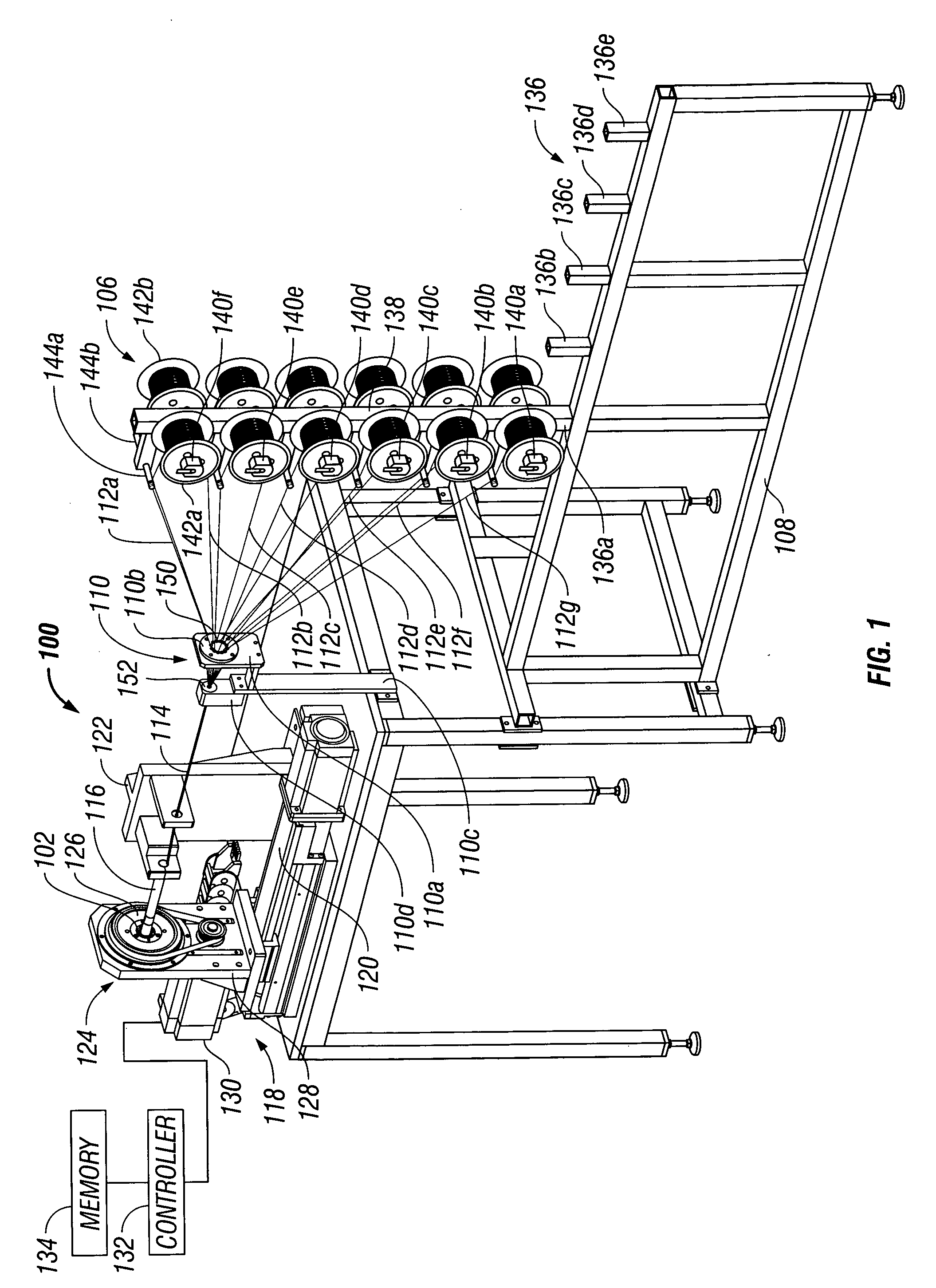
[0030]Turning now to FIG. 1, there is shown an apparatus 100 configured for internally winding a stator 102. One example of a stator 102 is shown in FIG. 9 in an enlarged view and has a number of inner axially disposed slots 104. The apparatus 100 is configured for manufacturing a plurality of wound stators 102 one after another in a sequential or at least partially automated manner. It is envisioned that the slots 104 of stator 102 (FIG. 9) may be linearly disposed in the stator 102 or include other configurations such as a herringbone, axially disposed or include a sinusoidal configuration. Generally, the apparatus 100 includes a feeding assembly 106 disposed on a stand 108. The apparatus 100 also has a bundling assembly 110 configured to feed a wire, or more preferably a bundle of a number of strands of conductive wire 112a through 112g from the feeding assembly 106 and for forming a single conductive wire bundle...


PUM

PropertyMeasurementUnit
Angleaaaaaaaaaa
Shapeaaaaaaaaaa
Electrical conductoraaaaaaaaaa

Abstract

An apparatus for manufacturing an internal wound stator includes a winding arbor configured to receive a conductive wire. The apparatus also has a stator loader with a stator having a generally cylindrical shape with an interior opening and having a plurality of axial slots formed therein. The interior dimension of the stator is larger than the exterior dimension of the winding arbor such that the winding arbor and stator may traverse with respect to one another. The apparatus also has a first movable member configured for moving at least one of the winding arbor and the stator. The apparatus also has a second rotating member configured to rotate at least one of the stator and the winding arbor. The conductive wire is introduced through an interior of the winding arbor. The first movable member is configured to move at least one of the winding arbor and the stator relative to one another to wind the conductive wire in a first longitudinal manner and into a first of the plurality of axial slots. The second rotating member is configured to rotate at least one of the first winding arbor or the stator relative to one another to align the wire relative to a second axial slot of the plurality of axial slots. The first movable member is configured to move at least one of the winding arbor and the stator relative to one another to wind the conductive wire in a second opposite longitudinal manner and into the second axial slot.

Description

RELATED APPLICATION[0001]This application claims the benefit of U.S. Provisional Patent Application No. 60 / 831,508, filed on Jul. 18, 2006, which is herein incorporated by reference in its entirety.BACKGROUND OF THE INVENTION[0002]The present invention relates to the manufacture of electric machines, such as a motor or a generator, and in particular to a machine that automates a wire winding of a stator. Manufacturing machines typically involve time and labor in order to wind or wrap wires around and / or within the axial slots of a stator. Such machines are costly and often involve complicated assemblies, which require a great deal of post manufacturing finishing operations in order to complete the stator. Accordingly, there is a need in the art for a manufacturing apparatus that is cost effective and that can rapidly manufacture a number of stators in a quick and automated manner.SUMMARY OF THE INVENTION[0003]According to a first embodiment, there is provided an apparatus for manufa...

Claims


Application Information

Patent Timeline
IPC IPC(8): H01F7/06
CPCH02K15/085Y10T29/49071Y10T29/53143Y10T29/49009
Inventor JONES, ROBERT M.LISIECKI, JOSEPH M.
Owner JONES ROBERT M
Why Eureka
Try Eureka