Hybrid vehicle control apparatus

a technology of vehicle control and hybrid technology, applied in the direction of engine-driven generators, instruments, transportation and packaging, etc., can solve the problems of affecting the operation of the vehicle control apparatus, and causing the seized or fixed of the second engaging elemen

Active Publication Date: 2008-01-24
NISSAN MOTOR CO LTD
View PDF11 Cites 64 Cited by
  • Summary
  • Abstract
  • Description
  • Claims
  • Application Information

AI Technical Summary

Problems solved by technology

However, operating the engine at or above the minimum rotational speed would result in too much power being delivered to the drive wheels.
However, if the slip control of the second engaging element is executed when the second engaging element is heated, there is the possibility that the second engaging element will seize or fix due to further heating.
If normal slipping control is executed without detecting that the second engaging element is seized, then the following problems could possibly occur.
First, unintended engine braking could occur during coasting, thus degrading the driving performance.
Second, when the engine is started and the drive mode is switched from the motor drive mode to the engine drive mode, there is the possibility that a change in the drive force of the motor / generator will be transmitted to the output shaft and cause the drive force imparted to the drive wheels to change.
Third, when the vehicle is set into motion from a stopped state using the engine in conjunction with the motor / generator, there is the possibility that the slip control will not result in sufficient slippage of the second engaging element, and the engine will stall or unpleasant vibrations will occur.

Method used


Image

  • Hybrid vehicle control apparatus
  • Hybrid vehicle control apparatus
  • Hybrid vehicle control apparatus

Examples


Embodiment Construction

[0028]Selected embodiment of the present invention will now be explained with reference to the drawings. It will be apparent to those skilled in the art from this disclosure that the following descriptions of the embodiment of the present invention is provided for illustration only and not for the purpose of limiting the invention as defined by the appended claims and their equivalents.

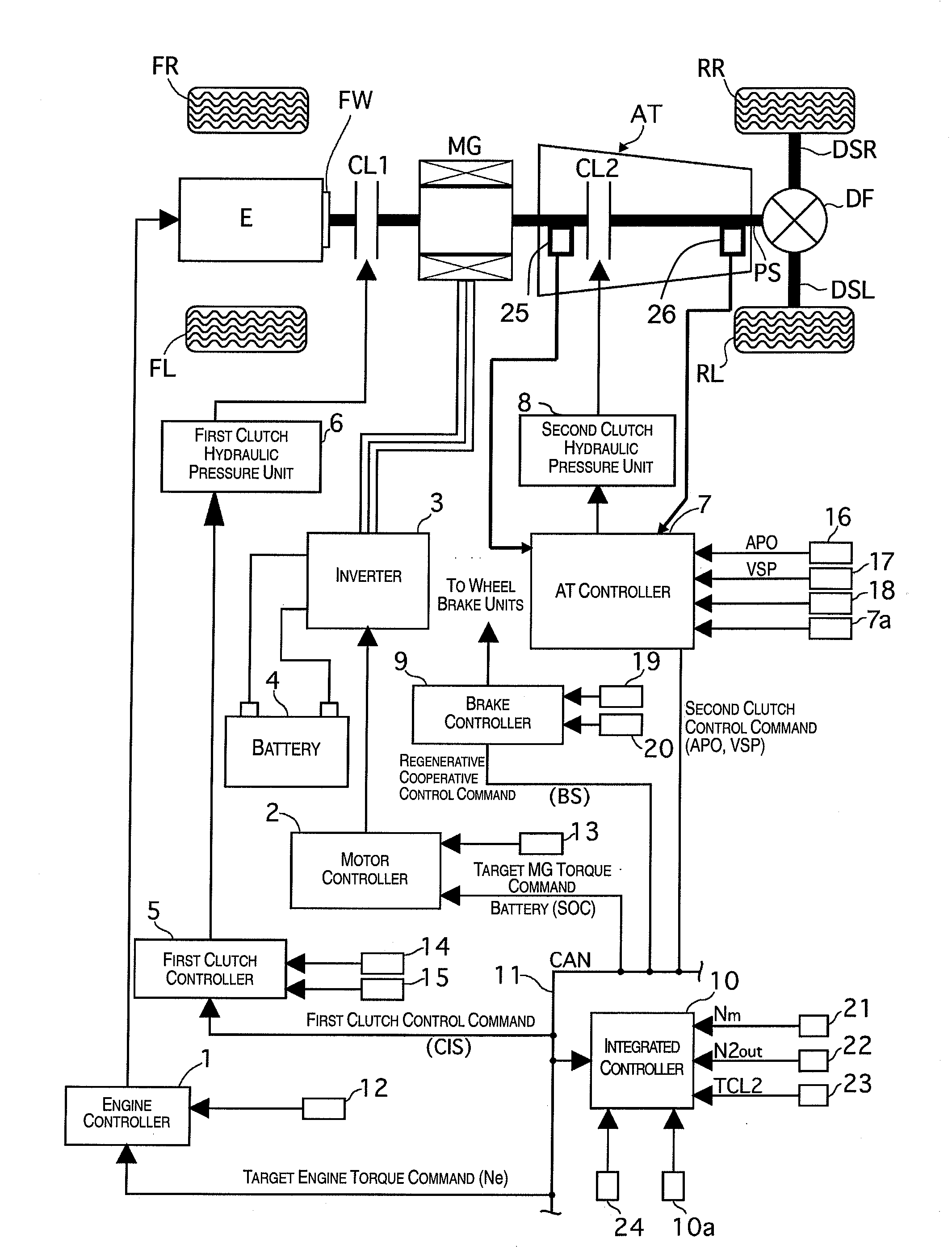
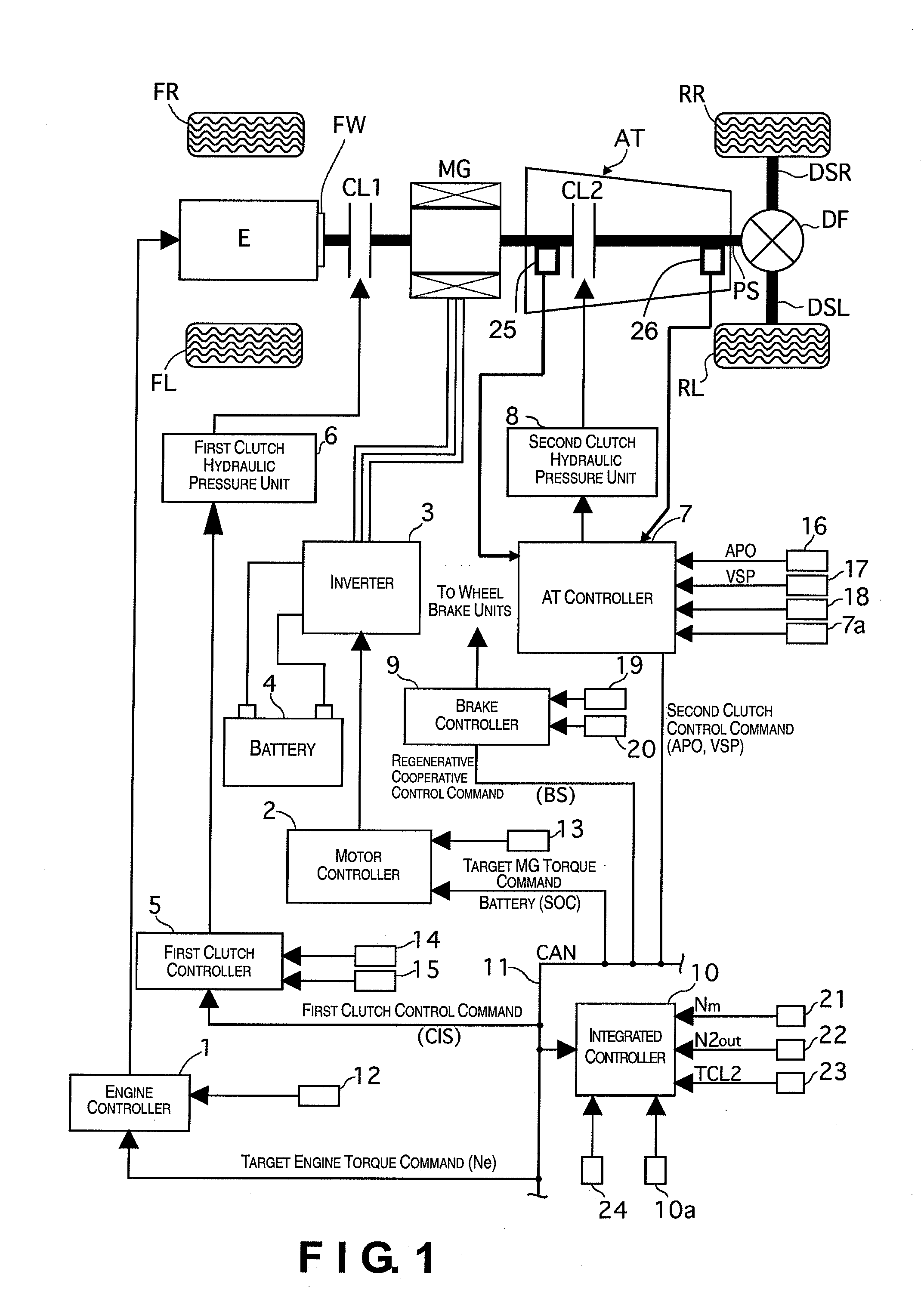
[0029]Referring initially to FIG. 1, a drive train of a hybrid vehicle having a hybrid vehicle control apparatus in accordance with an illustrated embodiment of the present invention is explained. In this example, the hybrid vehicle is arranged as a rear wheel drive hybrid vehicle. FIG. 1 is an overall schematic block diagram showing a drive train control system of the hybrid vehicle. As shown in FIG. 1, the drive train of the hybrid vehicle in the illustrated embodiment includes an internal combustion engine E, a first clutch CL1 (first engaging element), a motor / generator MG, a second clutch CL2 (se...


PUM


Abstract

A hybrid vehicle control apparatus includes an engine, a motor, first and second engaging elements, an input rotational speed and a controller. The first engaging element is arranged between the engine and the motor to selectively connect and disconnect the engine and the motor. The second engaging element is arranged between the motor and a drive wheel to selectively connect and disconnect the motor and the drive wheel. The input rotational speed detecting section is configured to detect an input rotational speed of the second engaging element corresponding to a rotational speed of the motor. The controller is configured to determine whether the second engaging element is seized based on the input rotational speed when a disengagement command or a slip engagement command has been issued to the second engaging element and a drive force of at least one of the engine and the motor has been changed.

Description

CROSS-REFERENCE TO RELATED APPLICATIONS[0001]This application claims priority to Japanese Patent Application Nos. 2006-198942, filed on Jul. 21, 2006 and 2007-149864, filed on Jun. 6, 2007. The entire disclosure of Japanese Patent Application Nos. 2006-198942 and 2007-149864 are hereby incorporated herein by reference.BACKGROUND OF THE INVENTION[0002]1. Field of the Invention[0003]The present invention relates to a hybrid vehicle control apparatus for a hybrid vehicle having an engine and a motor as power sources.[0004]2. Background Information[0005]Japanese Laid-Open Patent Application Publication No. 2001-255285 discloses a conventional hybrid vehicle having a first engaging element that selectively engages or disengages an engine and a motor, and a second engaging element that selectively engages or disengages the motor and a drive wheel. The conventional hybrid vehicle operates in one of a motor drive mode in which the motor alone is used as a power source and a hybrid drive mod...

Claims


Application Information

Patent Timeline
Patent Type & Authority Applications(United States)
IPC IPC(8): B60K6/00G06F7/00B60K6/48B60K6/547B60L50/16B60W10/02B60W10/06B60W10/08B60W10/10B60W20/00F16D48/02F16H59/40F16H59/42F16H59/70F16H61/12F16H61/68F16H61/684F16H61/686F16H63/40F16H63/50
CPCB60K6/365B60K6/48B60K6/547B60W10/06Y02T10/6286B60W10/115B60W20/00B60W2710/025Y02T10/6221B60W10/08Y10S903/914Y02T10/62B60W20/40
Inventor NAKANOWATARI, JUN
Owner NISSAN MOTOR CO LTD
Why Eureka
Try Eureka