Lubricant gun

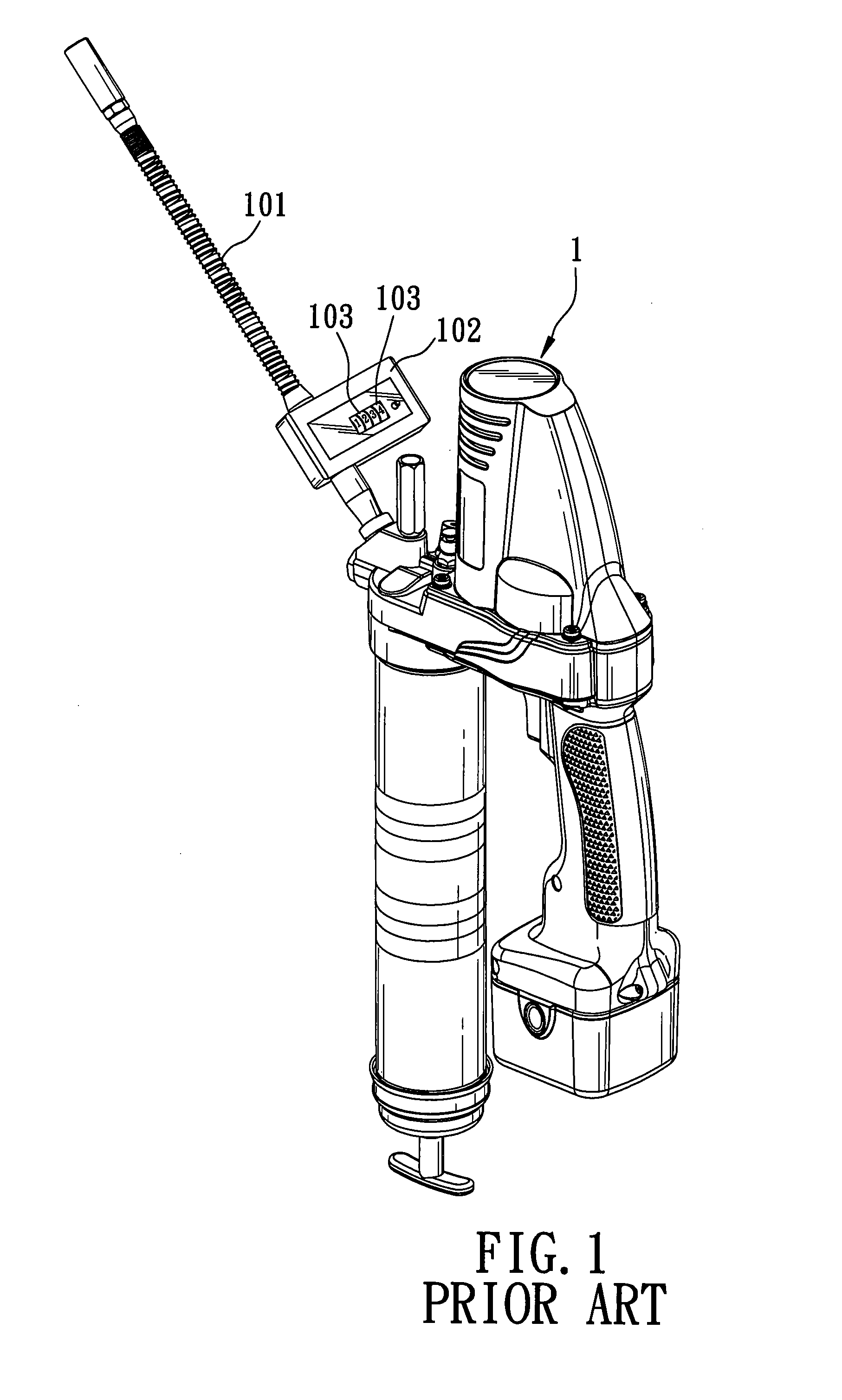
a technology of lubricant gun and lubricating element, which is applied in the direction of lubrication element, manual lubrication, conduit/junction, etc., can solve the problems of b>102/b> components that constitute the counter being liable to be abraded and eventually destroyed

Inactive Publication Date: 2008-01-24
TECHWAY INDAL
View PDF6 Cites 20 Cited by
  • Summary
  • Abstract
  • Description
  • Claims
  • Application Information

AI Technical Summary

Problems solved by technology

However, since the pressure for discharging the lubricant is significantly high, usually in a range from 6,000 to 10,000 psig, the components that constitute the counter 102 are liable to be abraded and eventually destroyed.

Method used


Image

  • Lubricant gun
  • Lubricant gun
  • Lubricant gun

Examples


Embodiment Construction

[0019]Before the present invention is described in greater detail, it should be noted that like elements are denoted by the same reference numerals throughout the disclosure.

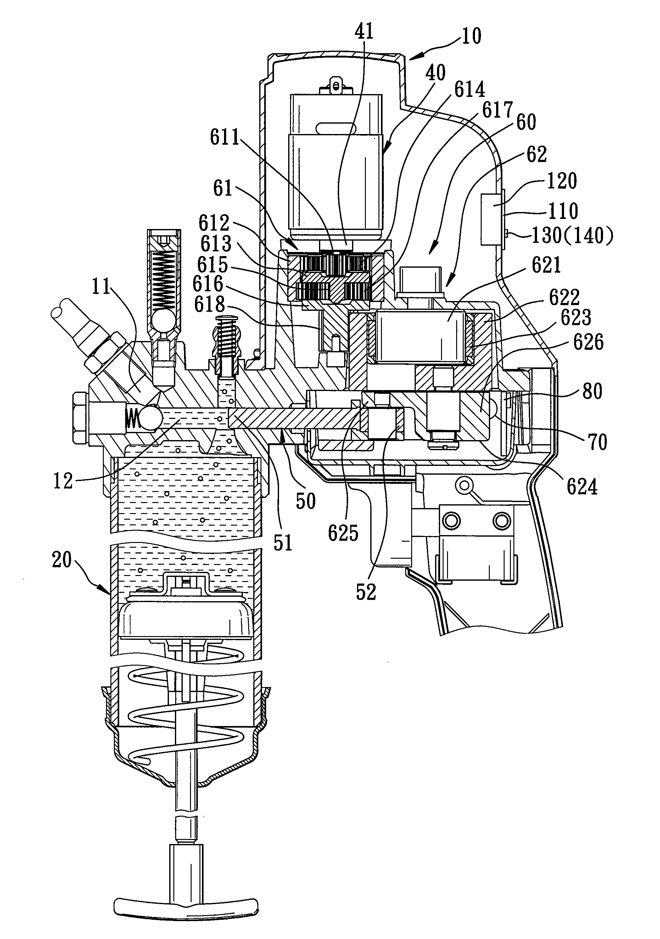
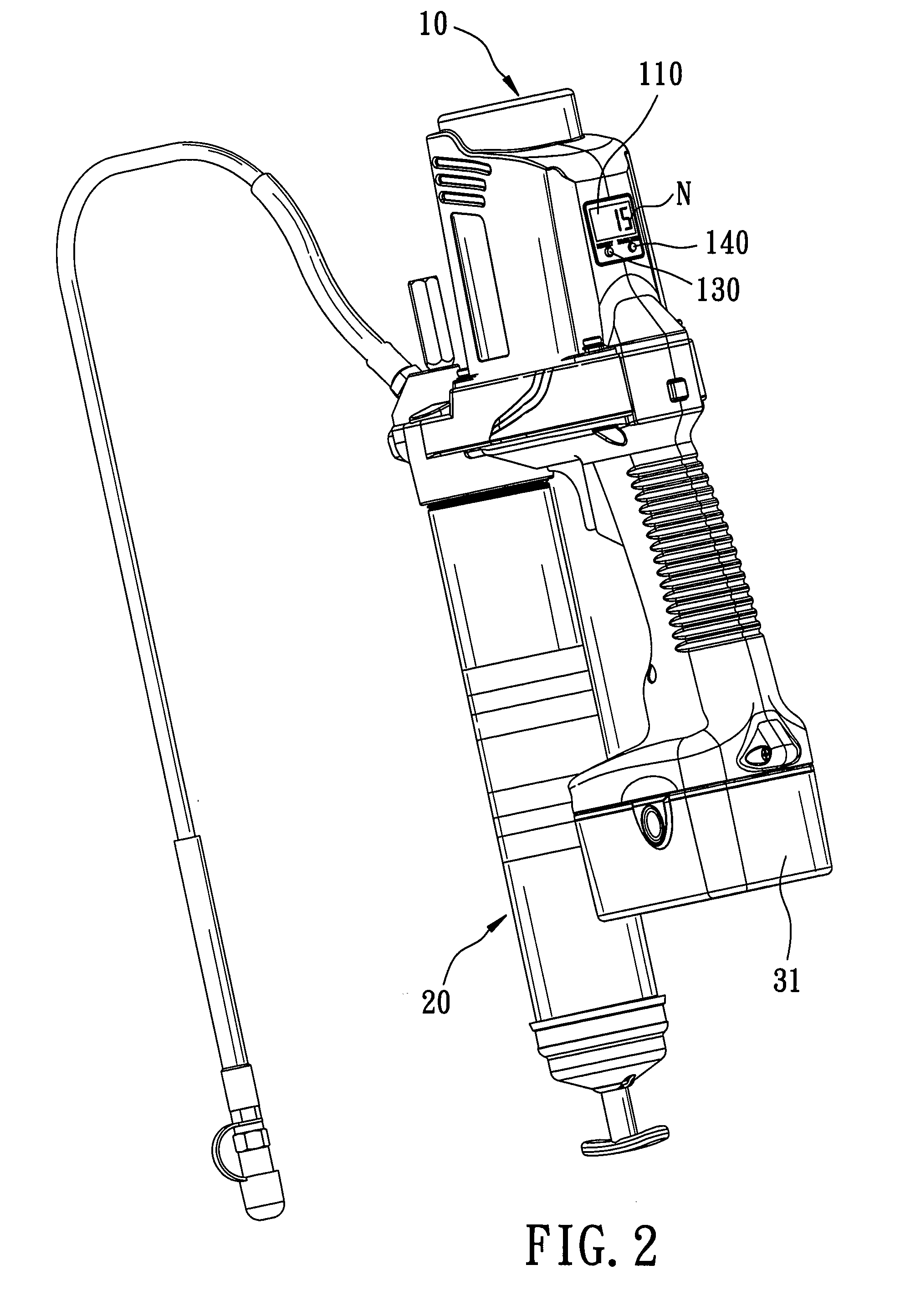
[0020]Referring to FIGS. 2, 3, and 4, the first preferred embodiment of a lubricant gun according to this invention is shown to include a housing 10, a lubricant reservoir 20, a power supply unit 30, a motor 40, a plunger 50, a power transmission unit 60, a moving element 70, a sensor 80, a processing unit 90, and a display unit 100.

[0021]The housing 10 includes a discharge spout 11, and a longitudinal slide channel 12 fluidly communicating with the discharge spout 11.

[0022]The lubricant reservoir 20 is connected to the housing 10 and provides a supply of lubricant into the longitudinal slide channel 12.

[0023]The power supply unit 30 includes a battery 31 and a power supplier 32 connected electrically to the battery 31.

[0024]The motor 40 is mounted within the housing 10, and is connected electrically to the batt...


PUM


Abstract

A lubricant gun includes: a housing having a discharge spout and a longitudinal slide channel; a motor; a plunger disposed in the longitudinal slide channel to perform reciprocating movements; a power transmission unit driven by the motor to actuate the plunger, and including a crank connected to the plunger; a moving element movable along with the crank and the plunger to perform a cycle motion; a sensor mounted proximate to a moving path of the moving element to detect the moving element whenever the moving element moves past the sensor, and to generate a signal representative of a number of the cycle motions performed by the moving element; a processing unit connected to the sensor to produce information according to the signal generated by the sensor; and a display unit displaying the information produced by the processing unit.

Description

CROSS-REFERENCE TO RELATED APPLICATION[0001]This application claims priority of Taiwanese application No. 095124468, filed on Jul. 5, 2006.BACKGROUND OF THE INVENTION[0002]1. Field of the Invention[0003]The invention relates to a lubricant gun, more particularly to a lubricant gun having a counting function.[0004]2. Description of the Related Art[0005]Referring to FIG. 1, a conventional lubricant gun 1 includes a lubricant transporting hose 101 and a mechanical type of counter 102 mounted on the lubricant transporting hose 101. The counter 102 includes a plurality of vanes (not shown) and a plurality of counting rollers 103 linked to the vanes. When lubricant is transported via the lubricant transporting hose 101, the lubricant will drive the vanes to rotate the counting rollers 103 so as to display the amount of the lubricant discharged via the lubricant transporting hose 101.[0006]However, since the pressure for discharging the lubricant is significantly high, usually in a range f...

Claims


Application Information

Patent Timeline
Patent Type & Authority Applications(United States)
IPC IPC(8): F16N21/00
CPCF16N29/00F16N3/12
Inventor CHEN, LI-CHI
Owner TECHWAY INDAL
Why Eureka
Try Eureka