Ink jet printer

a jet printer and ink jet technology, applied in printing, other printing apparatus, etc., can solve the problem of unstable ink tank contraction in the vertical direction, and achieve the effect of stabilizing the ink tank contraction amoun

Inactive Publication Date: 2008-01-24
BROTHER KOGYO KK
View PDF35 Cites 14 Cited by
  • Summary
  • Abstract
  • Description
  • Claims
  • Application Information

AI Technical Summary

Benefits of technology

[0009] According to the aforementioned construction, the ink tank can be caused to elastically deform (contract) in the vertical direction by applying a pushing force to the ink tank in the vertical direction. The member is arranged in a position adjacent to the predetermined side surface of the ink tank. Because of this, the ink tank will come into contact with the member, even if the ink tank swells in the horizontal direction when the ink tank is caused to

Problems solved by technology

The amount of contraction in the ink tank in the vertical direction will not be stable when the afor

Method used


Image

  • Ink jet printer
  • Ink jet printer
  • Ink jet printer

Examples


first embodiment

[0035] An embodiment will be described with reference to the drawings. Note that the embodiment described below is simply one example of the present invention. The embodiment described below can be suitably changed within a scope that does not change the essence of the present invention.

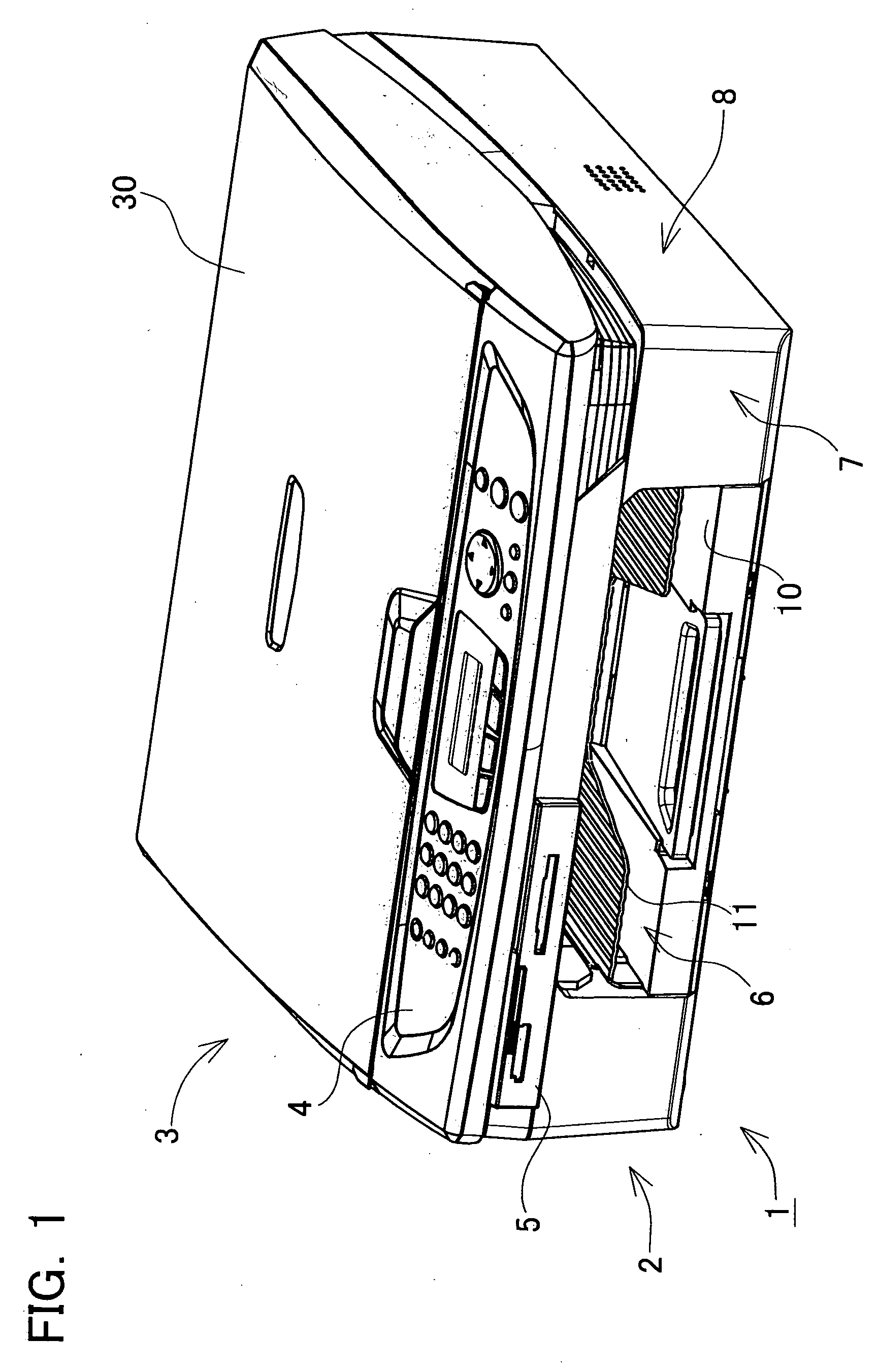
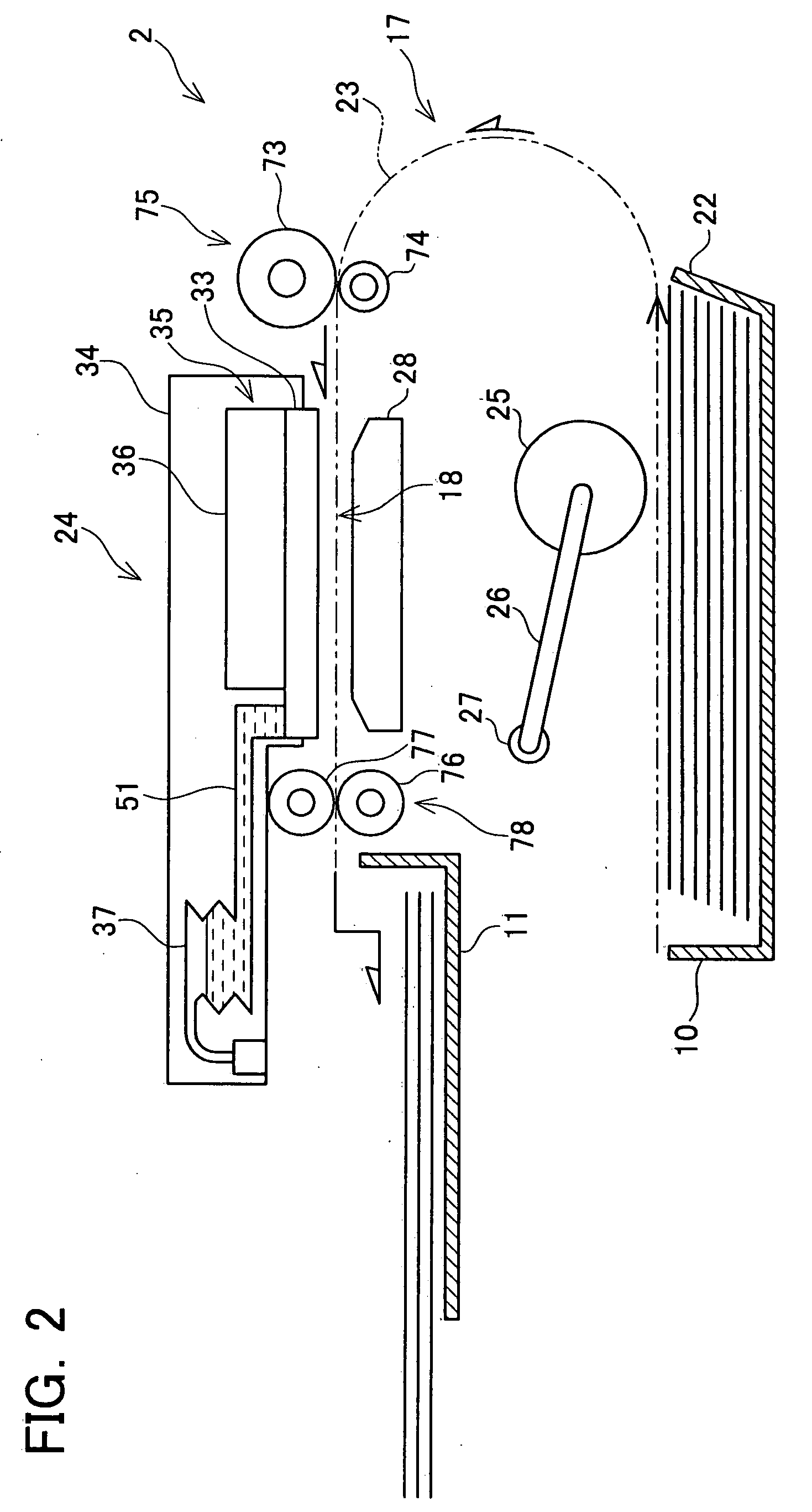
[0036]FIG. 1 shows an oblique view of a multi-function device 1. The multi-function device 1 comprises a printer unit 2 and a scanner unit 3. The printer unit 2 is located above the scanner unit 3. The multi-function device 1 has a print function, a scan function, a copy function, a facsimile function, and the like. The printer unit 2 is an ink jet type.

[0037] The multi-function device 1 may be connected to and used with an external information processing device such as a computer or the like. The multi-function device 1 can print images and text on a print medium (e.g., a printing sheet) based upon print data including image data and text data transmitted from a computer or the like. The multi-fun...

second embodiment

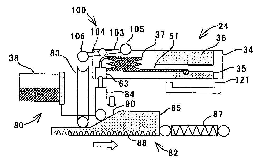
[0132]FIG. 24 shows a simple cross-sectional view of a printer unit 2 of a third embodiment. In FIG. 24, the same reference numbers as the first embodiment will be used for the same elements as the first embodiment. In the present embodiment, the ink cartridges 138 and the sub tanks 137 are always connected when the ink cartridges 138 are mounted to the printer unit 2. The ink cartridges 138 and the sub tanks 137 are connected by tubes 139 having elasticity. The ink cartridges 138 and the sub tanks 137 are also connected when the head 35 is printing on printing sheets. Thus, ink can be supplied from the ink cartridges 38 to the sub tanks 137 even when the head 35 is printing on printing sheets. Note that the sub tanks 137 are elastically deformable (the fact that they are bellows shaped) as in the first embodiment. In other words, ink can be supplied from the ink cartridges 138 to the sub tanks 137 by pressing the sub tanks 137 just as in the first embodiment. In addition, like in t...

third embodiment

[0133]FIG. 25 shows a simple cross-sectional view of a printer unit 2 of a third embodiment. In FIG. 25, the same reference numbers as the first embodiment will be used for the same elements as the first embodiment. In the present embodiment, the ink cartridges 238 are detachably mounted on the carriage 34. When the carriage 34 moves in a state in which the ink cartridges 238 are mounted on the carriage 34, the carriage 34 will move together with the ink cartridges 238. In the present embodiment, the ink cartridges 238 are constructed to be elastically deformable in the vertical direction. For example, the ink cartridges 238 have a bellows shape. The aforementioned regulators 68 (not shown in FIG. 25) are provided in positions adjacent to the ink cartridges 238.


PUM


Abstract

An ink jet printer is provided with an ink jet head, an ink tank, an actuator, and a member. The ink jet head has an ink passage and a nozzle communicating with the ink passage. The ink tank communicates with the ink passage of the ink jet head. The ink tank is elastically deformable along a vertical direction. The actuator is capable of applying a pushing force to the ink tank in the vertical direction. The member is located at a position which is adjacent to a predetermined side surface of the ink tank.

Description

CROSS-REFERENCE TO RELATED APPLICATION [0001] This application claims priority to Japanese Patent Application No. 2006-182874, filed on Jul. 1, 2006, the contents of which are hereby incorporated by reference into the present application. BACKGROUND OF THE INVENTION [0002] 1. Field of the Invention [0003] The present invention relates to an ink jet printer that will print on a print medium by discharging ink. Note that the word “printer” used in the present specification is to be interpreted in the broadest sense, and is a concept that includes a facsimile device, a copy machine, a multi-function device, and the like. [0004] 2. Description of the Related Art [0005] Ink jet printers are widely known. An ink jet printer comprises an ink jet head having an ink passage and a nozzle that communicate therewith. For example, an ink jet printer disclosed in Japanese Patent Application Publication No. 2004-358918 comprises a carriage on which an ink jet head is mounted. With this type of ink...

Claims


Application Information

Patent Timeline
IPC IPC(8): B41J2/175
CPCB41J2/17513B41J2/1752B41J29/38B41J29/02B41J2/17553
Inventor UMEDA, TAKAICHIRO
Owner BROTHER KOGYO KK
Why Eureka
Try Eureka