Liquid discharge head and method for manufacturing such head

Active Publication Date: 2006-05-11
CANON KK
View PDF18 Cites 12 Cited by
  • Summary
  • Abstract
  • Description
  • Claims
  • Application Information

AI Technical Summary

Benefits of technology

[0017] Therefore, an object of the present invention is to provide a liquid discharge head and a method for manufacturing such a head in which a discharging speed of a liquid droplet is increased and a discharging amount of the liquid droplet is stabilized, thereby enhancing discharging efficiency of the liquid droplet.
[0019] Further, the liquid discharge head having the above-mentioned construction is designed so that a height, a width or a sectional area of the flow path is changed in the nozzle and, an ink volume is gradually decreased along a direction directing from the substrate to the discharge port, and, in the vicinity of the discharge port, there is provided a configuration or structure in which, when the liquid droplet is flying, the flying liquid droplet directs toward a direction perpendicular to the substrate and is subjected to a straightening (rectifying) action. Further, when the liquid droplet is discharged, it is possible to suppress the liquid filled in the bubbling chamber from being pushed toward the supply path by the bubble generated in the bubbling chamber. Accordingly, according to this liquid discharge head, the dispersion in the discharging volume of the liquid droplet discharged from the discharge port is suppressed, thereby maintaining the discharging volume properly. Further, in this liquid discharge head, by providing a control portion constituted by a stepped portion, when the liquid droplet is discharged, since the bubble growing in the bubbling chamber strikes against an inner wall of the control portion in the bubbling chamber, loss of pressure of the bubble can be suppressed. Thus, according to this liquid discharge head, since the bubble in the bubbling chamber is grown in a good manner to ensure the adequate pressure, the discharging speed of the liquid droplet is enhanced.

Problems solved by technology

On the other hand, inherent disadvantages of this ink discharging method are that a volume of the flying ink droplet is changed when heat generated by the electrical / thermal converting element is accumulated in the liquid discharge head and that cavitation caused by extraction of the bubble affects a bad influence upon the electrical / thermal converting element and that, since air dissolved in the ink remains as residual bubbles, a bad influence is affected upon an ink droplet discharging property and image quality.
However, an upper surface of the flow path pattern formed by this method includes minute unevenness by the influence of scattering of exposing light.
Thus, there is inconvenience that the discharging amount of the ink droplet is decreased by reduction in volume of the ink in the bubbling chamber.
Further, in the conventional liquid discharge head, when the part of the ink filled in the bubbling chamber is pushed back toward the supply path, a part of pressure of the growing bubble facing to the supply port is escaped toward the supply path or is lost by friction between inner walls of the bubbling chamber and the bubble.
Thus, the conventional liquid discharge head has a problem that the discharging speed of the ink droplet is decreased by reduction pressure of the bubble.
Further, the conventional liquid discharge head also has a problem that, since the volume of the small amount of ink filled in the bubbling chamber is changed by the bubble growing in the bubbling chamber, the discharging amount of the ink is dispersed.

Method used


Image

  • Liquid discharge head and method for manufacturing such head
  • Liquid discharge head and method for manufacturing such head
  • Liquid discharge head and method for manufacturing such head

Examples


first embodiment

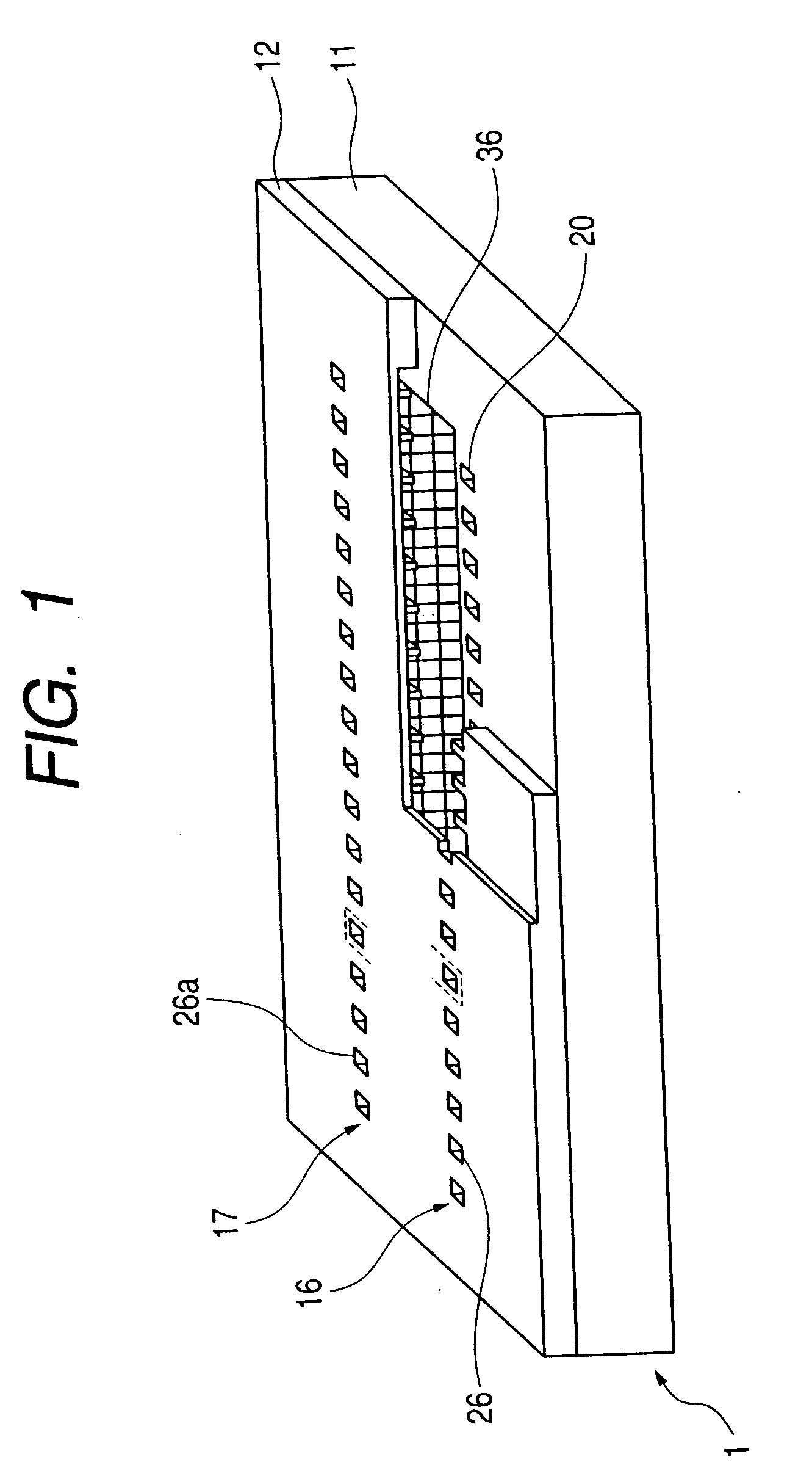
[0041] Although a detailed explanation will be made later, as shown in FIG. 1, in a liquid discharge head 1 according to a first embodiment of the present invention, partition walls for independently forming nozzles as ink flow paths for respective plural of heaters as heat generating resistance bodies extend from discharge ports to the vicinity of a supply port. Such a liquid discharge head includes ink discharging means using an ink jet recording method as disclosed in Japanese Patent Application Laid-Open Nos. 4-10940 and 4-10941 in which a bubble generated during the ink discharging is communicated with atmosphere via a discharge port.

[0042] The liquid discharge head 1 includes a first nozzle array 16 having plural heaters and plural nozzles and in which longitudinal directions of the respective nozzles are in parallel with each other and a second nozzle array 17 opposed to the first nozzle array with the interposition of a supply chamber. In both of the first nozzle array 16 a...

second embodiment

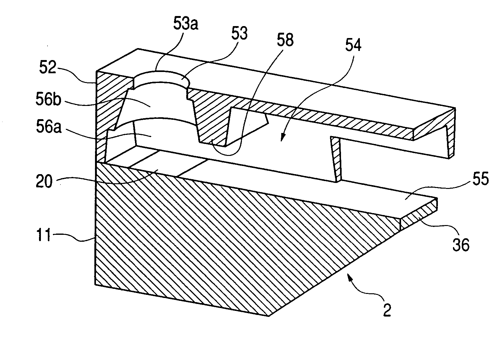
[0104] In the first embodiment, while an example that the second bubbling chamber 31b having the conical shape is formed above the first bubbling chamber 31a and the inclination of the side wall of the second bubbling chamber is converged toward the discharge port portion 26 with the angle of 10 to 45 degrees with respect to the plane perpendicular to the main surface of the element substrate 11 was explained, in a second embodiment of the present invention, a liquid discharge head 2 in which the ink filled in the bubbling chamber is apt to be shifted toward the discharge port will be explained. Incidentally, the same elements as those in the liquid discharge head 1 are designated by the same reference numerals and explanation thereof will be omitted.

[0105] In the liquid discharge head 2 according to the second embodiment, similar to the first embodiment, each bubbling chamber 56 includes a first bubbling chamber 56a in which a bubble is generated by a heater 20 and a second bubbli...

third embodiment

[0133] Now, a liquid discharge head 3 according to a third embodiment of the present invention in which the height of the first bubbling chamber of the above-mentioned liquid discharge head 2 is further decreased and the height of the second bubbling chamber is increased will be explained briefly with reference to the accompanying drawings. The same elements as those in the liquid discharge heads 1 and 2 are designated by the same reference numerals and explanation thereof will be omitted.

[0134] In the liquid discharge head 3 according to the third embodiment, similar to the first embodiment, each bubbling chamber 66 includes a first bubbling chamber 66a in which a bubble is generated by a heater 20 and a second bubbling chamber 66b disposed on the way from the first bubbling chamber 66a to a discharge port portion 63 and, inclination of a side wall of the second bubbling chamber 66b is converged toward the discharge port portion 63 with an angle of 10 to 45 degrees with respect to...


PUM


Abstract

The present invention provides a liquid discharge head and a method for manufacturing such a head, in which a discharging speed of a liquid droplet can be increased, a discharging amount of the liquid droplet can be stabilized and discharging efficiency of the liquid droplet can be enhanced. The liquid discharge head comprises a heater, an element substrate on which the heater is provided, a nozzle including a discharge port portion having a discharge port for discharging the liquid droplet and a bubbling chamber and a supply path for supplying the liquid to the bubbling chamber and a supply chamber for supplying the liquid to the nozzle and an orifice substrate and, the bubbling chamber includes a first bubbling chamber and a second bubbling chamber above the first bubbling chamber and the discharge port portion is communicated with the second bulling chamber via a stepped portion and a side wall of the second bubbling chamber is converged toward the discharge port with inclination of 10 to 45 degrees and the nozzle is provided with a control portion comprised of a stepped portion in the flow path in the vicinity of the bubbling chamber and a maximum height of the flow path is smaller than a height up to a lower surface of the discharge port portion.

Description

BACKGROUND OF THE INVENTION [0001] 1. Field of the Invention [0002] The present invention relates to a liquid discharge head for recording an image on a recording medium by discharging a liquid droplet such as an ink droplet and a method for manufacturing such a head, and more particularly, it relates to a liquid discharge head for performing ink jet recording. [0003] 2. Related Background Art [0004] An ink jet recording system is one of so-called non-impact recording systems. [0005] In the ink jet recording system, noise generated during the recording is very small which is negligible and high speed recording can be achieved. Further, the ink jet recording system has advantages that the recording can be performed on various recording media so that ink can be fixed with respect to even a so-called normal or plain paper without requiring special treatment and that a highly fine image can be obtained with a low cost. Due to such advantages, the ink jet recording system has recently be...

Claims


Application Information

Patent Timeline
IPC IPC(8): B41J2/05B41J2/14B41J2/16
CPCB41J2/1404B41J2/1433B41J2/1603B41J2/1629B41J2002/14475B41J2/1637B41J2/164B41J2002/14403B41J2/1631B41J2/05
Inventor KUBOTA, MASAHIKOHIYAMA, WATARU
Owner CANON KK
Why Eureka
Try Eureka