Method and apparatus for recording image data

a technology of image data and recording method, which is applied in the field of recording process of image data, can solve the problems of shortening the time necessary for recording image data, requiring compression process and recording process, and increasing the amount of data to be recorded, so as to shorten the time taken for recording process

Inactive Publication Date: 2008-01-24
RICOH IMAGING COMPANY
View PDF10 Cites 31 Cited by
  • Summary
  • Abstract
  • Description
  • Claims
  • Application Information

AI Technical Summary

Benefits of technology

[0016]When the camera is capable of shooting continuously to obtain a series of captured images, to shorten the time taken by the recording process, the recording processor may record the original image data or the compressed image data regarding a first-captured image. Then, the recording processor records the remaining images so as to be similar to the firstly captured image.

Problems solved by technology

In the case of lossless coding, the amount of data to be recorded increases significantly when compared to a lossy (compression) coding with information loss.
On the other hand, when photographing, especially when carrying out a continuous shooting, shorting of the compression process and recording process is required to capture as many images as possible.
However, the lossless coding cannot effectively shorten the time necessary for recording image data because of the large amount of data to be recorded.

Method used


Image

  • Method and apparatus for recording image data
  • Method and apparatus for recording image data
  • Method and apparatus for recording image data

Examples


first embodiment

[0025]FIG. 1 is the rear view of a digital camera according to the

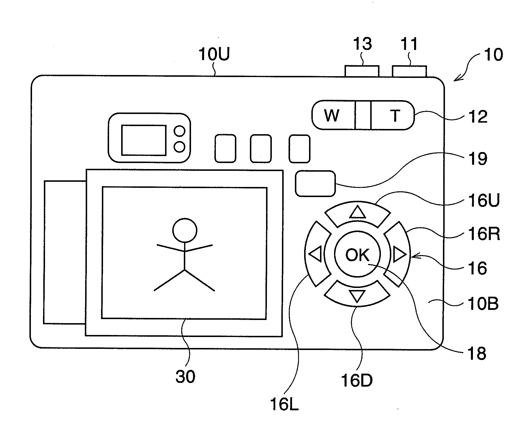
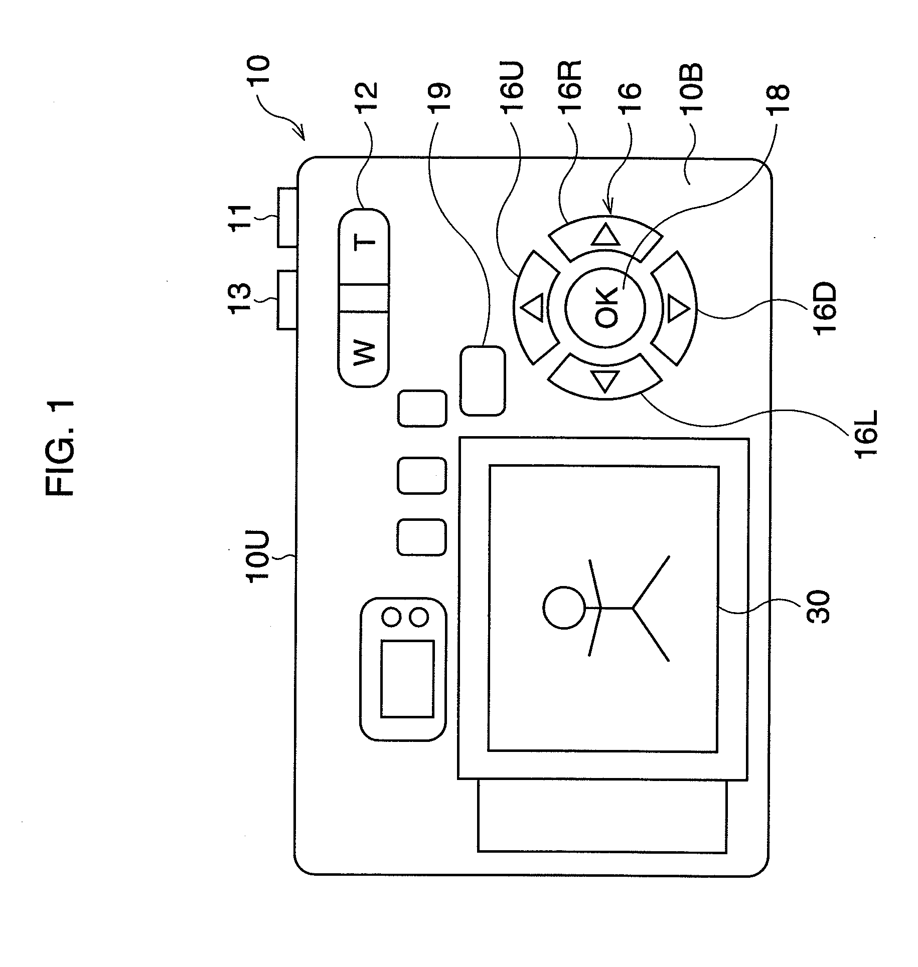
[0026]A digital camera 10 has an LCD monitor 30 on a back surface 10B, and a view finder 22 above the LCD monitor 30. Further, a series of buttons are provided on the back surface 10B. Herein, a zoom button 12; a cross-shaped button 16 composed of an up button 16U, a down button 16D, a right button 16R, and a left button 16L; an OK button 18; and a mode button 19, are provided. The mode button 19 is operated to switch between a plurality of modes including a photographing (shooting)-mode, a menu-mode, and a replay-mode.

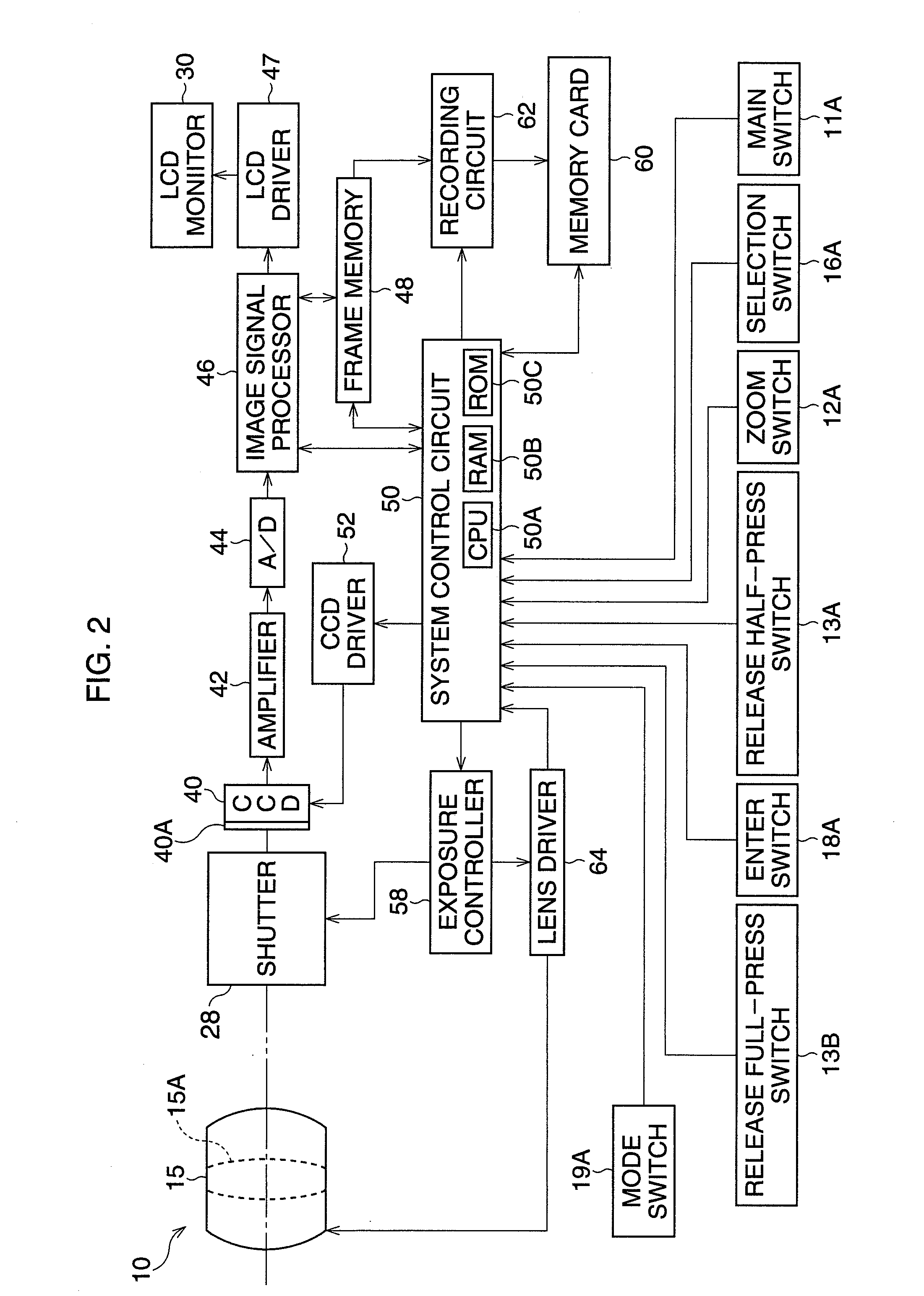
[0027]A main button 11 and a release button 13 are provided on an upper surface 10U. The camera 10 is turned ON by depressing the main-button 11, and an object image is recorded by operating the release button 13. In a lens barrel (not shown) provided on a front surface of the camera 10, a photographing optical system (herein, not shown) is installed.

[0028]In the photographing-mode for selecting the typ...

second embodiment

[0048]FIG. 5 is a flowchart showing the recording process according to the FIG. 6 is a view showing an image divided into a plurality of blocks.

[0049]In Step S201, a part of the original image data (RAW data), which is subjected to the recording process, is extracted. The image shown in FIG. 6 is divided into the plurality of blocks B, each block being composed of a plurality of predetermined pixels. Herein, a down sampling process is carried out on the basis of each block B, wherein blocks are extracted alternately in the horizontal and vertical directions, respectively. Thus, one out of two blocks among the horizontally-arrayed blocks, and one out of two blocks among the vertically-arrayed blocks, are extracted. In FIG. 6, the extracted blocks are represented by a slash. The part of image data to be extracted is read from the frame memory 48, and is fed to the recording circuit 62.

[0050]In Step S202, the Huffman coding is carried out on the extracted partial image data so that en...


PUM


Abstract

An apparatus for recording image data has an encoding processor that compresses original image data (for example, RAW data), having a plurality of pixels, in accordance with a lossless compression coding; and a recording processor that records the compressed image data or the original image data into a memory. If the size of the compressed image data is larger than that of the original image data, the recording processor records the original image data into the memory without carrying out a compression process.

Description

BACKGROUND OF THE INVENTION[0001]1. Field of the Invention[0002]The present invention relates to a digital camera, electronic equipment with a photographing function, and so on. In particular, it relates to a recording process of image data.[0003]2. Description of the Related Art[0004]In a digital camera, or a cellular phone with a photographing function, image data is encoded to decrease the amount of image data. High-quality image data, such as “RAW data”, can be encoded or compressed and recorded in a memory in accordance with a lossless (compression) coding. Thus, the original image data can be completely reconstructed from the compressed image data without information loss. In the JPEG lossless coding, a spatial coding is applied, wherein a difference value between neighboring pixels is successively calculated in accordance with the DPCM (Differential Pulse Code Modulation) fashion, and the difference value is subjected to the Huffman-Coding.[0005]In the case of lossless coding...

Claims


Application Information

Patent Timeline
Patent Type & Authority Applications(United States)
IPC IPC(8): H04N5/225G06K9/36H04N1/417H04N1/419H04N5/91H04N19/00H04N19/102H04N19/146H04N19/196H04N19/59H04N19/593H04N19/90H04N19/91H04N101/00
CPCH04N1/2112H04N5/772H04N9/7921H04N19/12H04N19/172H04N19/15H04N2101/00H04N5/262H04N1/41
Inventor KAWANAMI, NAOTO
Owner RICOH IMAGING COMPANY
Why Eureka
Try Eureka