Variable Focus Microlens

a microlense and variable focus technology, applied in the field of microlenses, can solve problems such as liquid evaporation, contact angle hysteresis, and limit their performan

Inactive Publication Date: 2008-01-24
AGENCY FOR SCI TECH & RES
View PDF9 Cites 67 Cited by
  • Summary
  • Abstract
  • Description
  • Claims
  • Application Information

AI Technical Summary

Problems solved by technology

However, various problems are associated with electrowetting-controlled fluidic microlenses, limiting their performance.
Such pro

Method used


Image

  • Variable Focus Microlens
  • Variable Focus Microlens
  • Variable Focus Microlens

Examples


Embodiment Construction

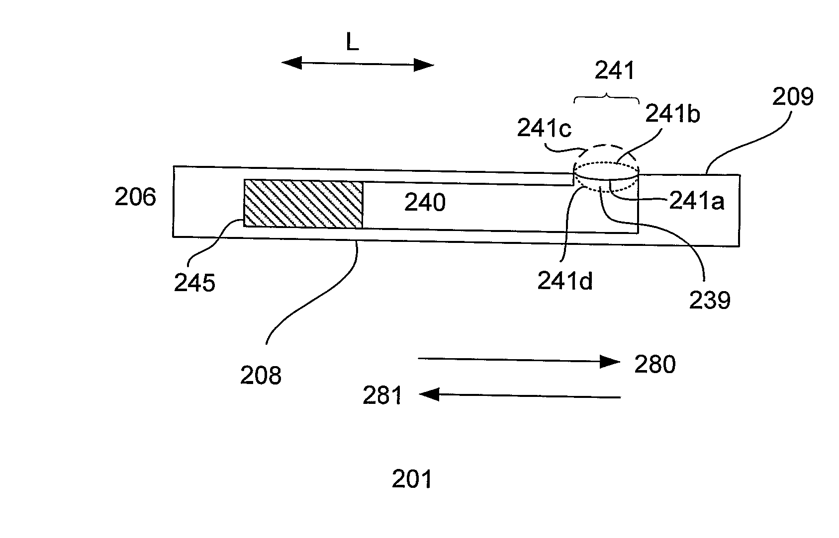
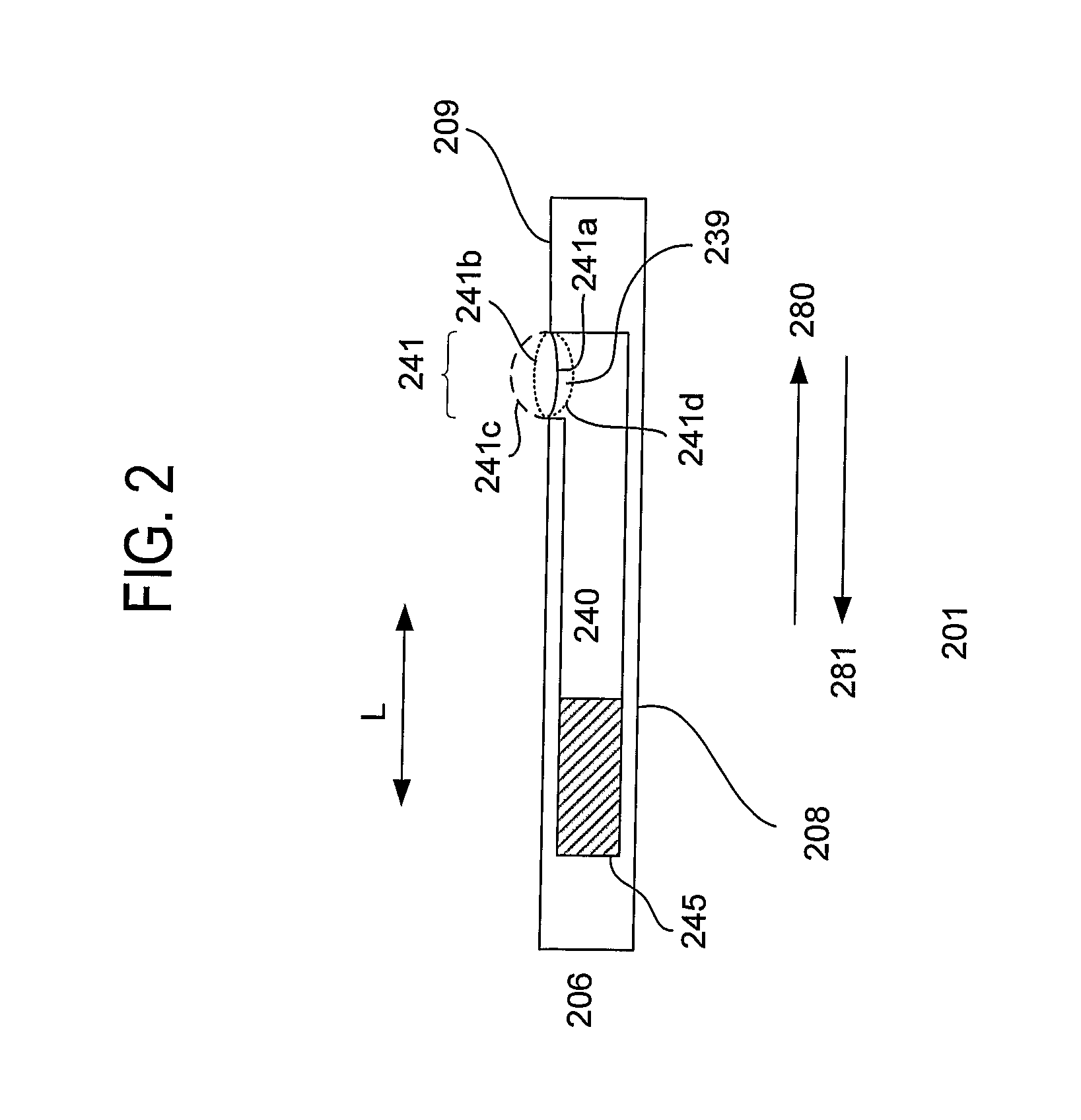
[0013] The present invention relates generally to fluidic microlenses. In one embodiment, the fluidic microlens is incorporated in a micro-electromechanical system (MEMS), to form a microlens chip. The microlens chip integrates both the lens and actuator. The microlens chip is conducive to micromachining processes. In accordance with one embodiment of the invention, actuation of the fluidic microlens (including formation and focusing) is achieved by changing fluid pressure. Other techniques for actuating the microlens are also useful.

[0014]FIG. 2 shows a cross-sectional view of a microlens chip 201 in accordance with one embodiment of the invention. As shown, the microlens chip comprises a package 206. Various materials can be used to form the package. For example, the package can be formed from glass, quartz, polymer, ceramic or a combination thereof. Other materials can also be useful. In one embodiment, the package is substantially rigid. Providing a flexible package is also use...


PUM


Abstract

A microlens chip comprises a variable focus fluidic microlens and actuator. The actuator varies the pressure in a fluidic channel in the microlens chip which is coupled to an aperture opening containing the microlens. Applying an electric field to the actuator creates changes in fluid pressure in the fluidic channel, which in turn changes the radius of curvature (i.e., focal length) of the fluidic microlens.

Description

FIELD OF THE INVENTION [0001] This invention relates to microlenses in general. More particularly, the invention relates to variable focus liquid microlenses. BACKGROUND OF THE INVENTION [0002]FIG. 1 shows a conventional fluidic microlens 101. As shown, the microlens comprises a substrate 110. The substrate includes a ground electrode 121 between first and second control electrodes 123a-b. The ground electrode is coupled to ground reference voltage while the control electrodes are coupled to variable voltage sources. Dielectric and coating layers 130 and 135 are disposed over the electrodes. The coating layer comprises a hydrophobic material, such as polytetrafluoroethylene (e.g., Teflon). The dielectric and coating layers are patterned to create a window 139, exposing the ground electrode. [0003] A drop of conductive liquid 140 is disposed on the coating layer. The drop serves as the microlens. The drop contacts the surface and ground electrode. In an inactive stage, (no voltage ap...

Claims


Application Information

Patent Timeline
IPC IPC(8): G02B3/12G02B7/04
CPCG02B3/14G02B3/12G02B3/00
Inventor FERNANDEZ, ISABEL RODRIGUEZMORAN, PETER M.KHAW, AIK HAUDHARMATILLEKE, SAMAN
Owner AGENCY FOR SCI TECH & RES
Why Eureka
Try Eureka