Zoom lens and projector unit

a zoom lens and projector technology, applied in the field of compact zoom lenses, can solve the problems of imposing limitations on projection lenses, the largest limitation in developing small projector units, and the limitation of the arrangement of light source systems

Inactive Publication Date: 2008-01-24
CASIO COMPUTER CO LTD
View PDF14 Cites 13 Cited by
  • Summary
  • Abstract
  • Description
  • Claims
  • Application Information

AI Technical Summary

Benefits of technology

[0013]In addition, in this zoom lens, the following conditional expression (1) is satisfied with respect to a power set at the first lens group, the following conditional expression (2) is satisfied with respect to a power set at the second lens group, and the following conditional expression (3) is satisfied with respect to an airspace set on a contracting side of the second lens group at the wide angle end;

Problems solved by technology

When the DMD is used as a light bulb in a projector unit, there are imposed limitations on a projection lens that is used at the same time, the limitations being specific to the DMD.
A first limitation is in relation to the f number of the projection lens, and this limitation is considered as the largest limitation in developing small projector units.
A second limitation relates to the arrangement of a light source system.
Since an image circle of the projection lens is desired to be decreased as much as possible in order to miniaturize the projector unit, the arrangement of an optical system for inputting rays of light for projection into the DMD is limited.
When considering this from the viewpoint of optical design of a projection lens, this constitutes a limitation on design of a projection lens in which the position of a pupil on the light bulb side has to be located in the vicinity of the rear of the projection lens.
Then, in the event that the overall length of the projection lens becomes long, in a lens in which the position of an entrance pupil lies at the rear thereof, a problem is caused that the size of a forward lens is naturally increased, and this contradicts the miniaturization.
A projection lens which has been developed to such a specification has a tendency that the aperture of a front group lens becomes larger than required in any ways, which comes to affect largely the thickness dimension of the projector unit.
In this example, however, an effective aperture of a front lens element when a 0.7-inch DMD is used is in the range of 39 mm to 42 mm, and the thickness of the projector unit cannot be decreased to 50 mm or less.
When actually carrying the projector unit with this thickness together with a note-type personal computer, the user has to feel that the relevant thickness is still unsatisfactory.

Method used


Image

  • Zoom lens and projector unit
  • Zoom lens and projector unit
  • Zoom lens and projector unit

Examples


embodiment 1

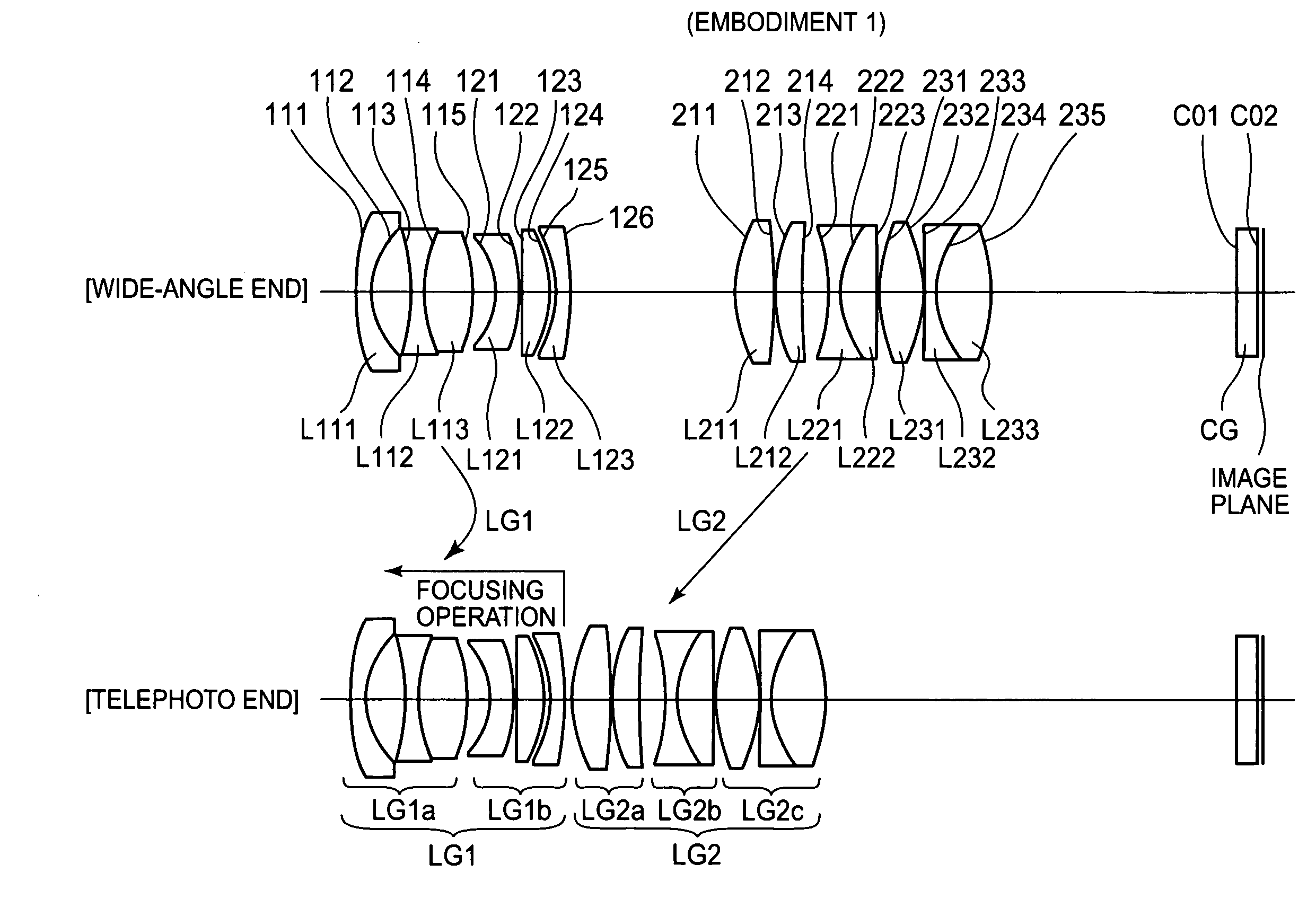
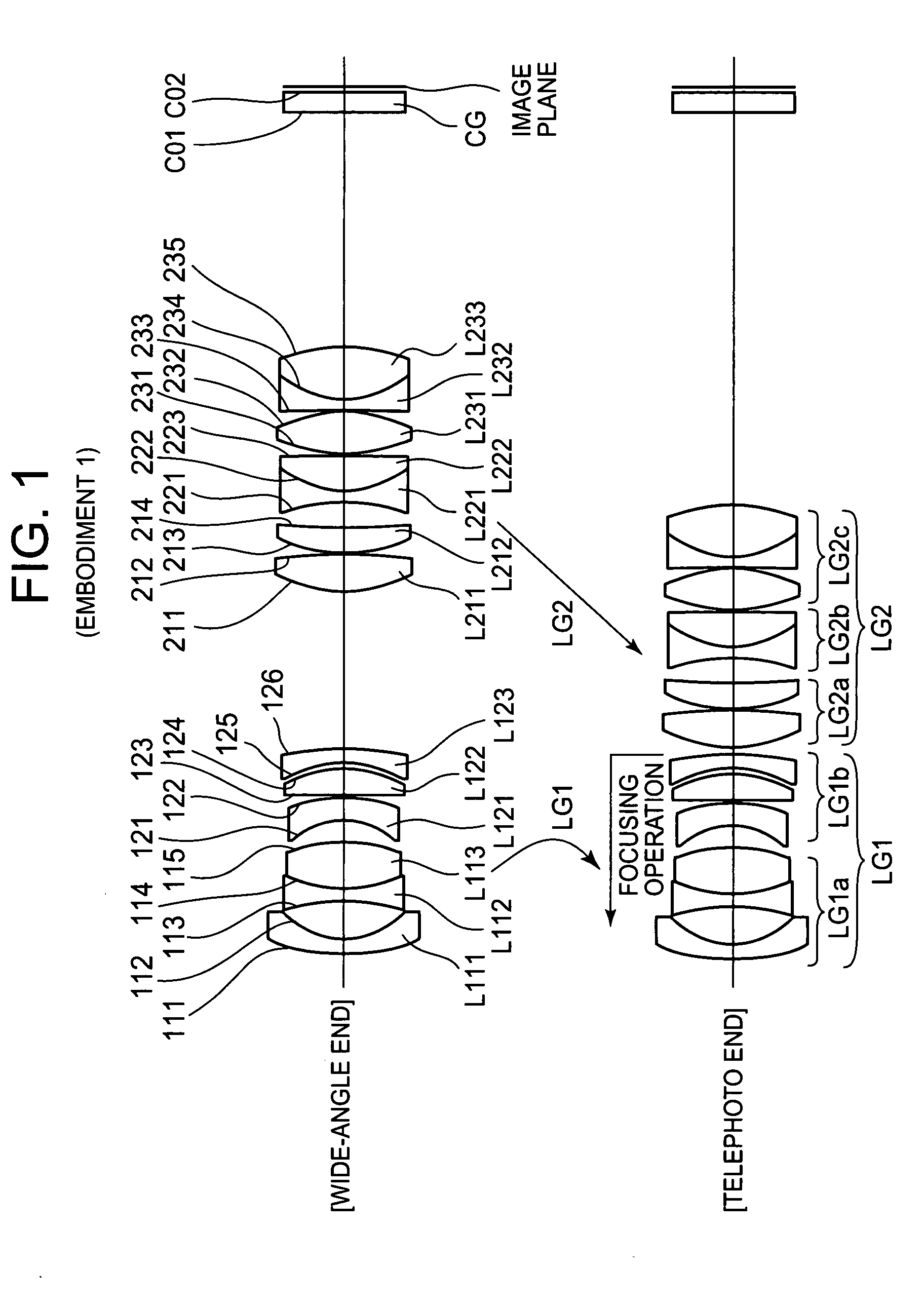
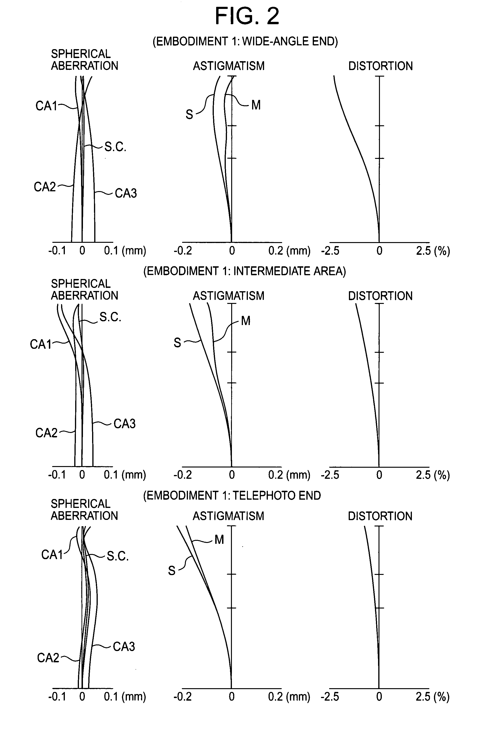
[0108]A numerical example for a first embodiment of a zoom lens of the invention is shown in Table 1. In addition, FIG. 1 is a drawing showing a lens configuration of the first embodiment and FIG. 2 shows drawings illustrating aberrations thereof. In the table and drawings, f denotes a focal length of the whole zoom lens system, Fno an f number, and 2ω a total angle of view of the zoom lens. In addition r denotes radius of curvature, d lens thickness or space between lens elements, nd a refractive index relative to the line d, and νd Abbe number of the line d (where, numerical values in the table which change by virtue of focusing operation are numerical values which result when an object distance from a surface 111 is 1700 mm in a focused state). CA1, CA2, CA3 in the spherical aberration drawings in the drawings showing aberrations are aberration curves in wavelengths of CA1=550.0 nm, CA2=435.8 nm and CA3=640.0 nm, respectively. In addition, S. C. is a sine condition. In aspherical...

embodiment 2

[0109]A numerical example for a second embodiment of a zoom lens of the invention is shown in Table 2. In addition, FIG. 3 is a drawing showing a lens configuration of the second embodiment and FIG. 4 shows drawings illustrating aberrations thereof.

TABLE 2Wide angle endIntermediate areaTelephoto endf15.9123.8630.74Fno2.292.723.232ω65.8246.1036.34Hereinafter, airspaces which change by variable powerD925.958.771.08D2134.3946.5957.22Serial numbersSurface numbersrdndνd111151.6312.321.8061040.73211214.9175.27——3113−84.6005.451.6968055.48411428.0039.381.6727032.175115−68.1232.20——6121−15.9084.991.7725049.657122−34.9070.20——8123674.5872.691.6932033.709124−59.759[D9]——1021127.3925.251.4970081.6111212−133.5270.20——1221334.4303.581.4874970.4513214222.5525.68——14221−36.2441.501.8042046.491522219.2635.271.5831359.4616223−169.9160.20——1723134.3076.411.5891361.2518232−28.0740.20——19233−225.6121.201.8042046.492023418.2967.701.4874970.4521235−39.714[D21]——22C01∞3.001.4874564.8423C02∞———Aspherical c...

embodiment 3

[0110]A numerical example for a third embodiment of a zoom lens of the invention is shown in Table 3. In addition, FIG. 5 is a drawing showing a lens configuration of the third embodiment and FIG. 6 shows drawings illustrating aberrations thereof.

TABLE 3Wide angle endIntermediate areaTelephoto endf15.9123.8830.76Fno2.292.733.402ω65.7846.0036.30Hereinafter, airspaces which change by variable powerD723.998.141.05D1934.0046.8658.04Serial numbersSurface numbersrdndνd111124.9352.071.8013945.45211212.1216.98——3113−32.5886.001.8061033.27411416.41811.18 1.7282528.315115−24.3711.46——6121−14.2863.501.8013945.457122−23.535[D7]——821129.7686.091.4874970.459212−165.0750.20——1021333.6994.081.4970081.6111214−655.3494.22——12221−43.4862.731.7725049.651322219.4165.361.5067070.5014223−160.6860.20——1523134.3008.051.4874970.4516232−27.3330.86——17233297.3921.201.8042046.491823419.8307.571.4874970.4519235−50.107[D19]——20C01∞3.001.4874564.8421C02∞———Aspherical coefficient111th surfaceK =−3.9661E+00A =5.6879...


PUM


Abstract

To provide a compact, high-performance zoom lens having a small lens aperture for enlarging an image from a light bulb such as a DMD for forming an image by changing a reflecting direction of light and projecting the image so enlarged on to a screen or the like, and the zoom lens includes, in order from a magnifying side, a first lens group having a negative refractive power as a whole and a second lens group having a positive refractive power as a whole, wherein changing the magnification of a whole lens system thereof is attained by configuring such that while a magnification varying operation is in effect, the first lens group and the second lens group are made to move on the optical axis.

Description

BACKGROUND OF THE INVENTION[0001]The present invention relates to a compact zoom lens having a small lens aperture for enlarging an image from a light bulb such as, mainly, a DMD (Digital Micromirror Device) for forming an image by changing a reflecting direction of light and projecting the image so enlarged on to a screen or the like and a projector which installs the zoom lens.[0002]In recent years, DMDs have been put into practical use in which fine micromirrors (mirror elements) are arranged on a plane in such a manner as to correspond to matching pixels and the angles of the respective micromirrors so arranged are mechanically controlled by the use of the micro-machine technology so as to form an image. Since the DMD is characterized in that it has a faster responding speed and can obtain a brighter image than the liquid crystal panel that has been widely used in this field and is, hence, suitable for realizing a portable projector unit which is small in size and which can prov...

Claims


Application Information

Patent Timeline
Patent Type & Authority Applications(United States)
IPC IPC(8): G02B15/14
CPCG02B15/177G02B3/0062G02B3/0087G02B3/04G02B2003/0093G03B21/142G02B15/1425
Inventor KAWAKAMI, ETSUROTEJIMA, YASUYUKI
Owner CASIO COMPUTER CO LTD
Why Eureka
Try Eureka