Packet processing device with load control mechanism based on packet length and CPU time consumption

a packet processing and load control technology, applied in the field of packet processing devices, can solve the problems of excessive packet processing overhead, degraded communication service quality, and explosion of packet traffic flowing over wireless networks, and achieve the effects of improving communication service quality, stable operation, and reducing the workload of packet processing

Inactive Publication Date: 2008-01-24
FUJITSU LTD
View PDF20 Cites 3 Cited by
  • Summary
  • Abstract
  • Description
  • Claims
  • Application Information

AI Technical Summary

Benefits of technology

[0009]In view of the foregoing, it is an object of the present invention to provide a packet processing device that achieves stable operation by alleviating the workload of packet processing and thus improves the quality of communication service.

Problems solved by technology

Mobile communication devices such as cellular phones are increasingly used in recent years, which leads to an explosive growth of packet traffic flowing over wireless networks.
In such circumstances, CPUs employed for packet processing are under a heavy load and thus experience firmware hang-up (freezing) problems more and more often, resulting in degraded quality of communication service.
This results in an excessive overhead of packet processing, which consumes more CPU-time resources than in the case of long packets, consequently affecting control tasks for other subsystems in the device.
As can be seen from the above discussion, an increase in the number of incoming short packets, or in the number of connection paths established at the packet processing device, will raise the CPU-time consumption.
This brings more chances for hang-up of packet processing, as well as causing adverse effect on other control tasks.
The conventional technique of reducing CPU load based only on the packet length is not effective enough to solve, or even alleviate, the problem.

Method used


Image

  • Packet processing device with load control mechanism based on packet length and CPU time consumption
  • Packet processing device with load control mechanism based on packet length and CPU time consumption
  • Packet processing device with load control mechanism based on packet length and CPU time consumption

Examples


Embodiment Construction

[0017]Preferred embodiments of the present invention will be described below with reference to the accompanying drawings, wherein like reference numerals refer to like elements throughout.

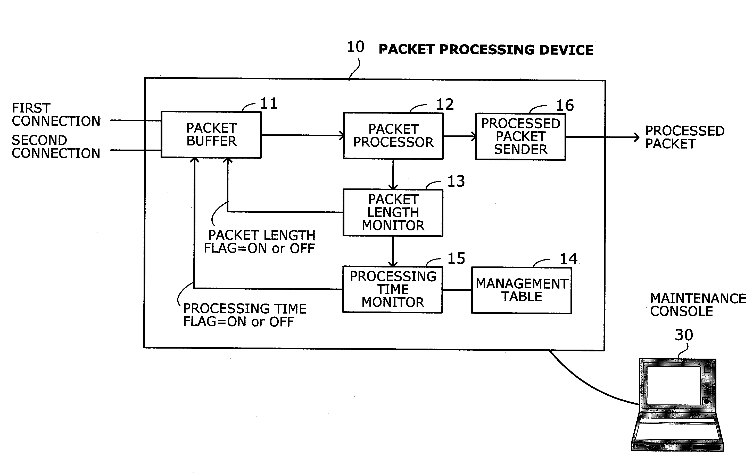
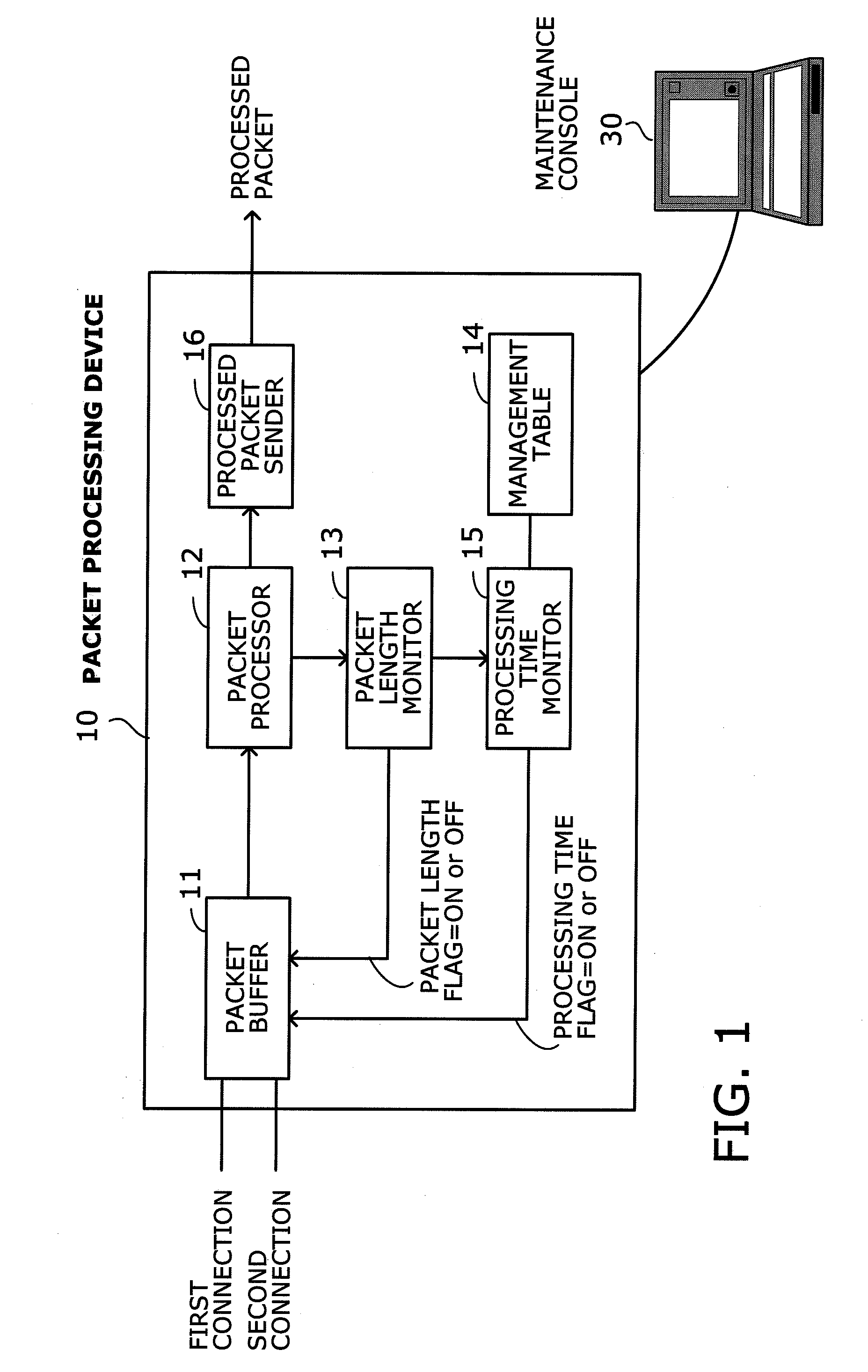
[0018]FIG. 1 is a conceptual view of a packet processing device according to the present invention. This packet processing device 10 is formed from a packet buffer 11, a packet processor 12, a packet length monitor 13, a management table 14, a processing time monitor 15, and a processed packet sender 16. For operations and maintenance purposes, a maintenance console 30 can be attached to the packet processing device 10.

[0019]The packet buffer 11 buffers either first packets on a first connection or second packets on a second connection that is different from the first connection. The packet buffer 11 initially focuses on the first connection and checks a packet length flag and a processing time flag to observe the condition of packet processing for the first connection. When neither of the two flag...


PUM


Abstract

A packet processing device that achieves stable operation by alleviating the workload of packet processing. A packet buffer checks a packet length flag and a processing time flag to observe the device's operating condition for a first connection. When neither of the two flags are on, the packet buffer keeps buffering first packets on the first connection. When either or both flags are on, the packet buffer changes focus to a second connection and begins buffering second packets on the second connection. A packet length monitor turns on the packet length flag if a new cumulative packet length is greater than a packet length threshold. A processing time monitor turns on the processing time flag if a new cumulative processing time estimate is greater than a predetermined processing time threshold.

Description

CROSS-REFERENCE TO RELATED APPLICATIONS[0001]This application is based upon and claims the benefits of priority from the prior Japanese Patent Application No. 2006-200358, filed on Jul. 24, 2006, the entire contents of which are incorporated herein by reference.BACKGROUND OF THE INVENTION[0002]1. Field of the Invention[0003]The present invention relates to packet processing devices and more particularly to a packet processing device that processes packets with firmware of a central processing unit (CPU).[0004]2. Description of the Related Art[0005]Mobile communication devices such as cellular phones are increasingly used in recent years, which leads to an explosive growth of packet traffic flowing over wireless networks. In such circumstances, CPUs employed for packet processing are under a heavy load and thus experience firmware hang-up (freezing) problems more and more often, resulting in degraded quality of communication service. For this reason, the packet processor in a radio n...

Claims


Application Information

Patent Timeline
Patent Type & Authority Applications(United States)
IPC IPC(8): H04L12/28H04L12/70
CPCH04L47/10H04L49/90H04L47/35H04L47/14H04W28/0247H04W28/0284H04W8/04
Inventor MIE, KOUKISHIMA, NOBUYUKI
Owner FUJITSU LTD
Why Eureka
Try Eureka