Method of controlling handover, base station and mobile station for use in a communication network

a communication network and mobile station technology, applied in the direction of wireless communication, electrical equipment, selection arrangements, etc., can solve the problems of large amount of signalling, inconvenient use, and inability to standardise the algorithm used for deriving handover decisions

Inactive Publication Date: 2008-01-24
ALCATEL LUCENT SAS
View PDF2 Cites 56 Cited by
  • Summary
  • Abstract
  • Description
  • Claims
  • Application Information

AI Technical Summary

Benefits of technology

[0010]It is the object of the present invention to provide a method of the above-defined type as well as a b...

Problems solved by technology

In the latter context, a particular problem concerning handover arises if base stations from different manufacturers are used in the RAN: a source base station currently serving a mobile station or user equipment performs a handover decision primarily based on measurement reports comprising quality-related radio link parameters from said user equipment (UE).
However, an algorithm used for deriving said handover decision generally...

Method used


Image

  • Method of controlling handover, base station and mobile station for use in a communication network
  • Method of controlling handover, base station and mobile station for use in a communication network
  • Method of controlling handover, base station and mobile station for use in a communication network

Examples


first embodiment

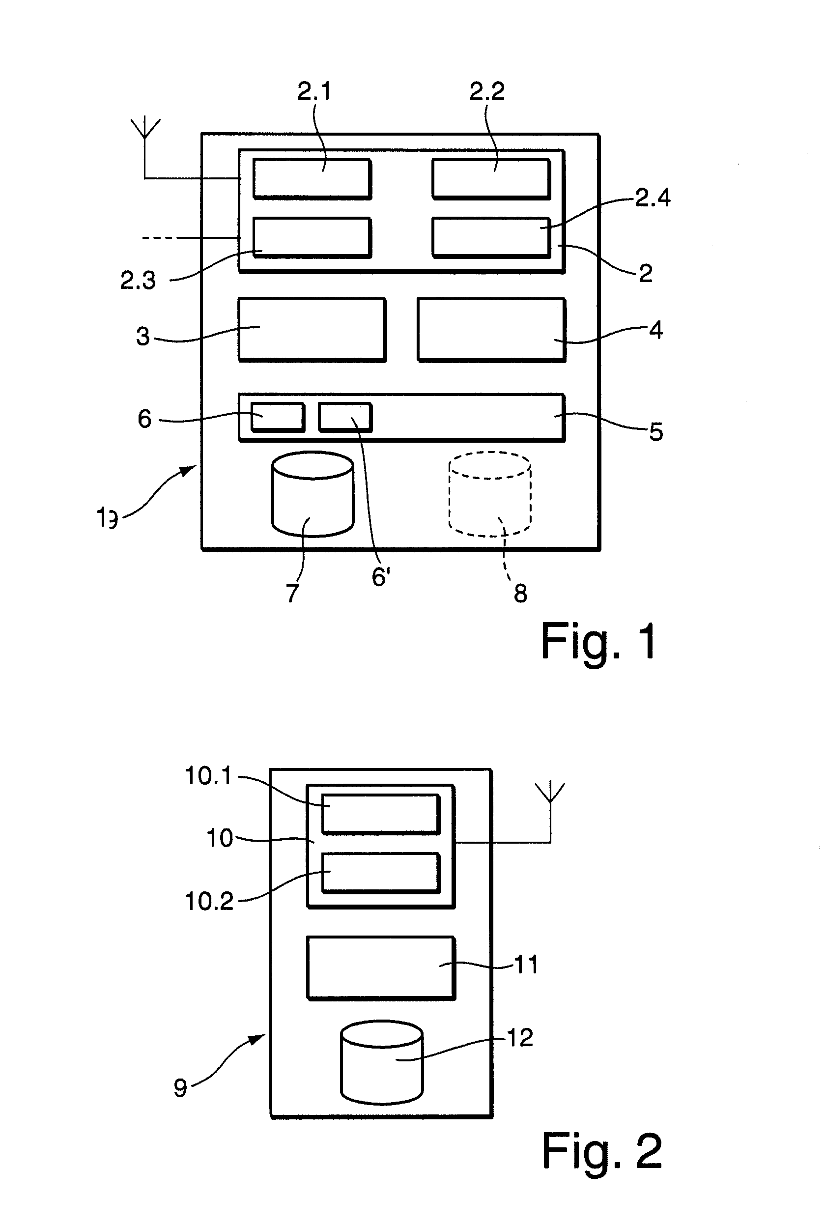
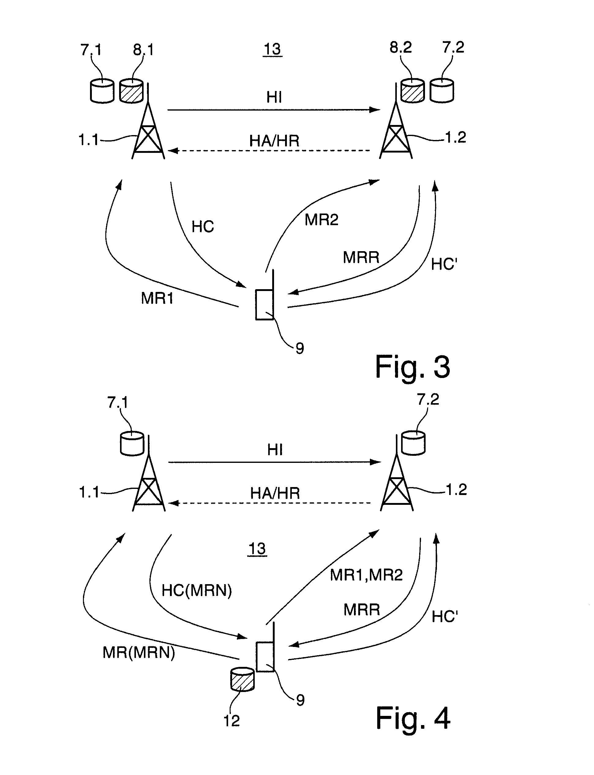
[0043]FIG. 3 shows a schematic signalling diagram for illustrating the method in accordance with the present invention. Referring to FIG. 3, there is depicted a mobile communication network 13 comprising user equipment 9 and first and second base stations 1.1, 1.2, respectively. Hereinafter, the first base station 1.1 will also be referred to as source base station, whereas the second base station 1.2 will also be referred to as target base station. As already stated above with reference to appended FIG. 1, in the embodiment of FIG. 3 said first and second base stations 1.1, 1.2 comprise first and second storing means 7.1, 7.2 and 8.1, 8.2, respectively. Hereinafter, said first storing means 7.1, 7.2 will also be referred to as load report database, and said second storing means 8.1, 8.2 will also be referred to as measurement report database with reference to their respective contents.

[0044]In the following it is assumed that UE 9 is in connected mode, can receive signals from sour...

second embodiment

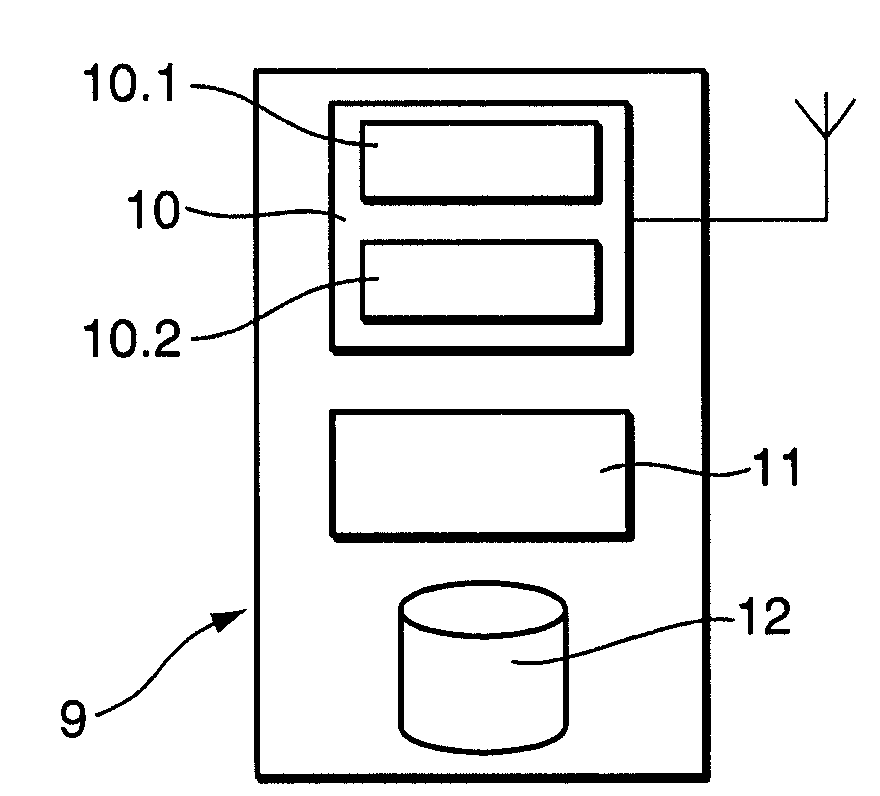
[0051]FIG. 4 shows a schematic signalling diagram for illustrating the method in accordance with the present invention. As can be gathered from the graphical representation in FIG. 4, the difference to the above-described embodiment of FIG. 3 is the location of measurement report databases. Whereas in FIG. 3 the measurement report database is located in a respective base station 1.1, 1.2, in the embodiment of FIG. 4 a single measurement report database 12 is located in UE 9, i.e., in each user equipment devised in accordance with an embodiment of the present invention (cf. FIG. 2).

[0052]In the embodiment of FIG. 4, a handover procedure for user equipment 9 is performed as follows:

[0053]UE 9 sends a first measurement report MR1 comprising a unique measurement report number MRN to source base station 1.1. UE 9 stores said measurement report MR1 and its number MRN for a certain time in measurement report database 12. If source base station 1.1 arrives at a handover decision, as previou...


PUM


Abstract

Method of managing mobility in a communication network wherein a mobile station is handed over from a source base station to a target base station, comprising:
providing the target base station with a first measurement report on radio link quality, comprising radio link quality measurements by the mobile station prior to said handover;
providing the target base station with a second measurement report on radio link quality, said second measurement report comprising radio link quality measurements by the mobile station after said handover;
in case of a proposed handover of the mobile station back to the source base station, comparing said first and second measurement reports;
during a predefined time interval, allowing the proposed handover only in case of an overload situation at the target base station and/or in case of differences between said first and second measurement reports which are above a predefined threshold.

Description

BACKGROUND OF THE INVENTION[0001]The invention is based on the priority application EP 06291173.0 which is hereby incorporated by reference.[0002]The present invention relates to a method of managing mobility in a communication network wherein a mobile station is handed over from a source base station to a target base station.[0003]The present invention further relates to a base station and to a mobile station for use in a communication network.[0004]A Radio Access Network (RAN) of, e.g., a Public Land Mobile Network (PLMN) can generally be realised with a centralised or with a decentralised architecture. Using a centralised architecture, a central node (e.g., Radio Network Controller (RNC) in UMTS (Universal Mobile Telecommunications System)) controls all of the base stations or at least a group of base stations in a communication network. The central node provides functions such as radio resource management, transmits power management, handover decisions, etc. for all radio cells ...

Claims


Application Information

Patent Timeline
IPC IPC(8): H04Q7/20H04W36/22H04W36/30
CPCH04W36/30H04W36/22H04W36/0033H04W88/02H04W88/08
Inventor HOFMANN, DIRK
Owner ALCATEL LUCENT SAS
Why Eureka
Try Eureka