Rotor blade form for producing a rotor blade of a wind power plant

a technology of wind power plants and molds, which is applied in the direction of mechanical control devices, instruments, paper/cardboard containers, etc., can solve the problems of exothermy, complicated and expensive heating systems, and high cost, and achieve the effect of reducing or shutting down heating operations, and rapid detection of rises in temperature in individual heating regions

Inactive Publication Date: 2013-04-25
WOBBEN PROPERTIES GMBH
View PDF7 Cites 6 Cited by
  • Summary
  • Abstract
  • Description
  • Claims
  • Application Information

AI Technical Summary

Benefits of technology

[0044]The solution according to the invention provides that it is also possible to react well to an exothermic operation which can occur for example upon hardening of resins because rapid detection of a rise in temperature in each individual heating region and rapid shut-down of each individual heating region is made possible.
[0045]Preferably the heating operation is reduced or shut down only when the measured temperature value exceeds the calculated temperature value by a predetermined minimum value which can also be temperature-dependent. That takes account on the one hand of a measurement inaccuracy and also a calculation inaccuracy, but a so-called ping-pong effect is also avoided.

Problems solved by technology

Such a heating system is really complicated and expensive in terms of production of the rotor blade mold provided therewith and complicated and expensive in terms of use as besides heating the water it is also necessary to provide for circulation thereof.
Furthermore, the problem of exothermy can occur when hardening resin.
In that case in the hardening operation the resin gives off heat to the environment, and that can lead to unwanted and uncontrolled heating and possibly overheating.
Sometimes it is only possible to inadequately counteract that phenomenon by interrupting the feed of further hot water.

Method used


Image

  • Rotor blade form for producing a rotor blade of a wind power plant
  • Rotor blade form for producing a rotor blade of a wind power plant
  • Rotor blade form for producing a rotor blade of a wind power plant

Examples


Embodiment Construction

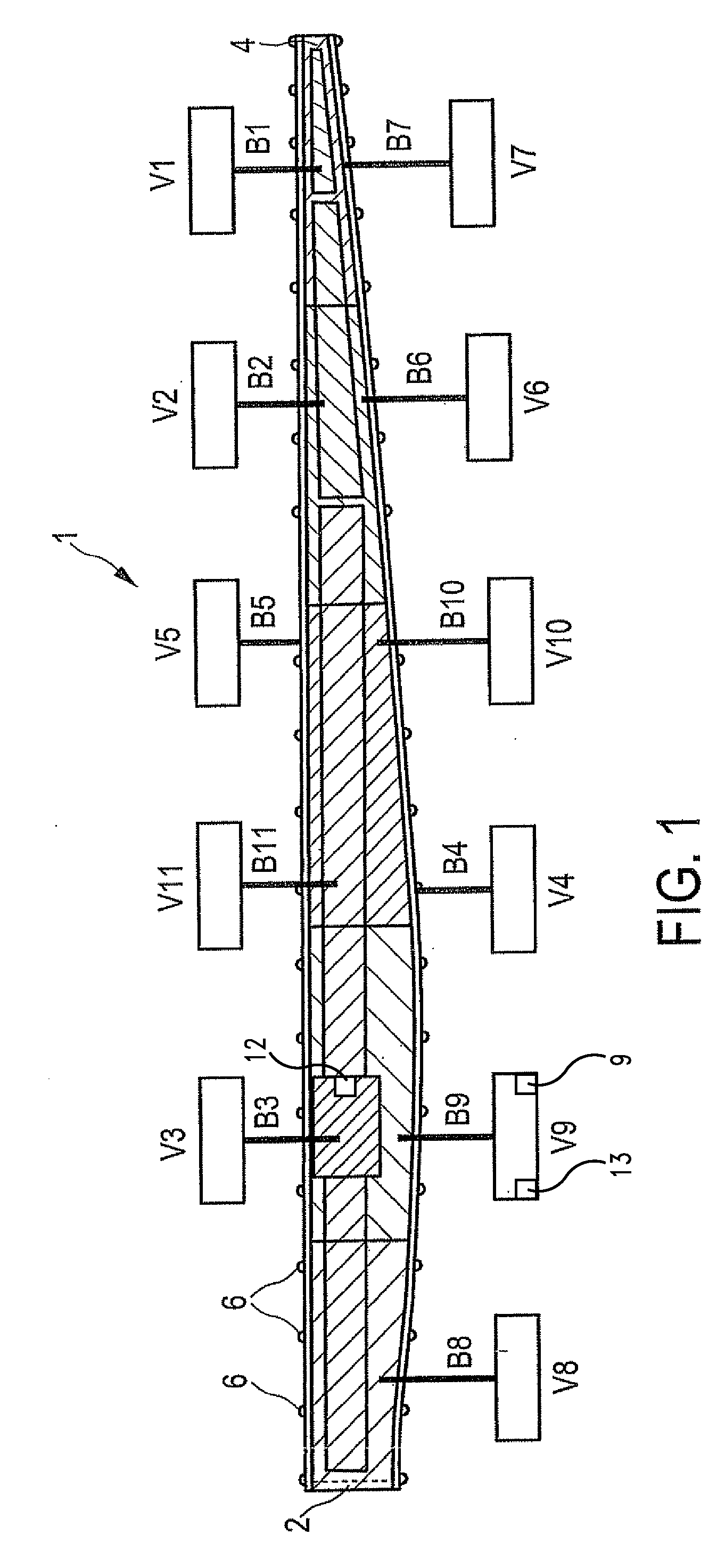
[0056]The rotor blade mold 1 in FIG. 1 is provided for producing a rotor blade half-shell. Two rotor blade half-shells can then be assembled to form a complete rotor blade after each half-shell has hardened in itself. The rotor blade mold 1 includes 11 heating regions B1 to B11 with 11 supply units V1 to V11. In accordance with the rotor blade to be produced, the rotor blade mold 1 has a root region 2 and a tip region 4, in which a root region of the rotor blade and the tip of the rotor blade are respectively correspondingly produced. FIG. 1 also shows portions of reinforcing bars 6 at their respective ends. FIG. 1 shows a view of the open rotor blade mold 1 and thus substantially a shaping surface of the rotor blade mold 1.

[0057]The rotor blade mold 1 is divided in length, namely from the root region 2 to the tip region 4, into the five main heating regions B8, B9, B10, B6 and B7. Those main heating regions achieve in particular uniform heating of the complete rotor blade mold 1 in...


PUM

PropertyMeasurementUnit
widthaaaaaaaaaa
lengthaaaaaaaaaa
lengthaaaaaaaaaa

Abstract

The present invention concerns a rotor blade mold for producing a rotor blade of a wind power installation or a part thereof comprising a heatable mold portion having a shaping surface for shaping the rotor blade surface and wherein the heatable mold portion has at least two heating portions and each heating portion includes at least one electrical resistance heating element arranged at or beneath the shaping surface and a supply unit for supplying the at least one resistance heating element with electrical heating current.

Description

BACKGROUND[0001]1. Technical Field[0002]The present invention concerns a rotor blade mold for producing a rotor blade of a wind power installation and a method of producing a rotor blade of a wind power installation.[0003]2. Description of the Related Art[0004]Rotor blades of modern wind power installations attain sizes of 60 m in length, 5 m in width and 2 m in thickness and can possibly be even still larger. To achieve high stability with low weight such a rotor blade is frequently made from a fiber-reinforced plastic, in particular glass fiber-reinforced plastic (GRP). That includes the aspect that components of other materials can be included in the rotor blade, such as for example a trailing edge of metal or reinforcement materials in the rotor blade of wood. The predominant part of the rotor blade, in particular the shaping shell or shell portion thereof is however made from fiber-reinforced plastic. For that purpose, at least one rotor blade mold is used, which basically form...

Claims


Application Information

Patent Timeline
Patent Type & Authority Applications(United States)
IPC IPC(8): F03D1/06
CPCB29C33/02B29C70/446Y10T156/10Y02E10/721F03D1/0675B29L2031/082Y02E10/72Y02P70/50B29C33/38B29C35/02B29C70/44
Inventor HARMS, STEPHANKOLBE, UWEOVERLANDER, TORSTEN
Owner WOBBEN PROPERTIES GMBH
Why Eureka
Try Eureka